
Page 391 - Mechatronics for Safety, Security and Dependability in a New Era
P. 391
Ch75-I044963.fm Page 375 Tuesday, August 1, 2006 5:58 PM
Page 375
Tuesday, August 1, 2006
5:58 PM
Ch75-I044963.fm
375
375
illustrates an experimental example of detecting an error space for the Z axis. The same procedure can
be applied to the directions X and Y which are vertical to Z, and planelike error forms for the Xi and
Yj are constructed. Consequently, error space for 3 axes (X, Y, Z) is constructed. Then it is possible to
estimate error components for (X, Y, Z) at arbitrary points among the measurement range of a CMM.
The points on which errors are directly measured are discrete. The error at an arbitrary point can be
obtained by applying interpolation or least squares method (LSM). When the error e z(X, Y, Z) is
obtained by interpolation or LSM, the compensation of the error is easily performed by subtracting the
from Z. By applying the method, the measurement accuracy is improved without any change of
e z
hardware configuration.
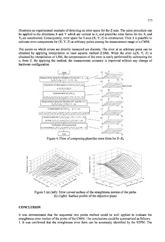
Measurement along the direction ofX axis for j=0. ••-. m
Z x(Xj,Y|.Z 0) (i=0.-,];j=0,-,m)
Calculation of decrepancy A from Z X (X|,Y 0 ,ZQ)
ZxpCl.Yo.Zo)
A=Z X(X I,Y,,,Z O)/I
Compensation of A for Z x
Z x (X i ,Yj,Z 0 )=Z x (X i ,Yj,Zn)4A (i=0,-.
Measurement along the direction ofY axis for i=0.
ZytXj.Yj.Zp) (i=0,l;j=0,-,m)
Compensation of A for Z v (j=l,-%m)
y(X 0,Y j,Z 0)=Z y(X 0,Y j,Z 0HA,Z y(X 1,Yj,Z 0)=Z y(X 1,Y j,Z 0HA
Compensation for Z^X^YJ.ZQ ) (i=0.-.l:j=l.--.m)
SO that Z x (X () .Yj.Z 0 )=Z y (X 0 .Yj,Z 0 ) (j=l.-.m)
Verification of measurement
by comparing Z X (X|.YJ ; ZQ) and Z (X hYyZQ) (j=0.-,m)
Figure 4: Flow of composing planelike error form for Z=Zo
15
) )
(µm (µm 10
r 0.5 r
o
r o r 5
r r
e 0
e
s s
s s
e -0.5 e 0
n n
t t
h h
g -1 g
i i
a a -5
r r
t t
S -1.5 S
350 400
-10
300 350
250 300 -15
200 250 400
150 200 300 300
n 150 200
100 Feed along X-axis (mm) 200
100
100
50 50 Feed along Y-axis (mm) 100 Feed along X-axis (mm)
0 0 0 0
Feed a lo g Y-a i x s ( mm)
Figure 5 (a) (left): Error curved surface of the straightness motion of the probe
(b) (right): Surface profile of the objective plane
CONCLUSION
It was demonstrated that the sequential two points method could be well applied to evaluate the
straightness error motion of the probe of the CMM. The conclusions could be summarized as follows.
1. It was confirmed that the straightness error form can be accurately identified by the STPM. The