Page 392 - Mechatronics for Safety, Security and Dependability in a New Era
P. 392

Ch75-I044963.fm  Page 376  Tuesday, August 1, 2006  5:58 PM
            Ch75-I044963.fm
               376
               376    Page 376  Tuesday, August  1, 2006  5:58 PM
                 measurement operation can be easily extended to planelike error  form.
                 An  algorithm  which  constructs  planelike  error  form  from  a bundle  of the  straightness  error  forms
                 was  demonstrated,  in which  a method  that  gives  conditions  at  the both  ends  of the  error  forms  is
                 proposed.
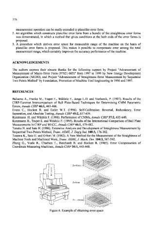
                 A  procedure  which  derives  error  space  for  measurable  range  of  the  machine  on  the  basis  of
                 planelike  error  forms  is  proposed.  This  makes  it  possible  to  compensate  error  among  the  total
                 measurement range, which certainly improves the accuracy performance  of the machine.


               ACKNOWLEDGEMENTS

               The  authors  express  their  sincere  thanks  for  the  following  support  by  Project  "Advancement  of
               Measurement  of  Macro  Error  Form  (97S21-005)"  from  1997  to  1999  by New  Energy  Development
               Organization  (NEDO),  and  Project  "Advancement  of  Straightness  Error  Measurement  by  Sequential
               Two Points Method" by Foundation,  Promotion of Machine Tool Engineering  in  1996 and  1997.


               REFERENCES
               Balsamo  A.,  Franke  M.,  Trapet  E.,  Waldele  F.,  Jonge  L.D.  and  Vanherck,  P. (1997).  Results  of  the
               CIRP-Euromet  Intercomparison  of  Ball  Plate-Based  Techniques  for  Determining  CMM  Parametric
               Errors, Annals  CIRP 46:1, 463-466.
               Evans  C,  Hocken  R.  and  Estler  W.T.  (1996).  Self-Calibration:  Reversal,  Redundancy,  Error
               Separation, and Absolute Testing, Annals  CIRP 45:2, 617-634.
               Kunzmann  H. and Waldele F. (1988). Performance  of CMMs, Annals  CIRP 37:2, 633-640.
               Kunzmann  H., Trapet  E. and Waldele  F. (1995). Results of the  International  Comparison  of  Ball  Plate
               Measurements in CIRP and WECC, Annals  CIRP 44:1, 479-482.
               Tanaka H. and  Sato H. (1986). Extensive  Analysis and Development  of  Straightness Measurement by
               Sequential Two-Points Method, Trans. ASME, J. Eng'glnd.  108:3, 176-182.
               Tozawa K.,  Sato H. and O-hori M. (1982). A New Method  for the Measurement  of the Straightness  of
               Machine Tools and Machined  Work,  Trans. ASME, J. Mack  Des. 104:3, 587-592.
               Zhang  G.,  Veale  R.,  Charlton  T.,  Borchardt  B.  and  Hocken  R.  (1985).  Error  Compensation  of
               Coordinate  Measuring  Machines, Annals CIRP 34:1, 445-448.


                                                       0.8
                                                       0.6
                                                       0.4 0.2 0
                                 s               Z=40mm  -  -0.2 -0.4 350 0 . 4 -0.6  300  250  200  200  250  300  350  400
                                                 Z=40mm
                                     R V A 6 0 0            150  100  50  0  0  50  100  150
                                     R
                                     R V A 6 0 0 009VAH
                                                        0.5 0
                                       I         Z=0mm  -0.5 -1.5 -1 350  400
                                    J
                                                 Z=0mm
                                                         300
                                                          250         300  350
                                                           200       250
                                                                    200
                                                            150
                                                                   150
                                                             100  100
                                                              50  50
                                                                0  0
                                    Z Z
                                  Y Y    X X
                                                         5
                                                         4
                                                        (   r o µ )  3
                                                        m
                                                         2 r r e   s s
                                                 Z= – 40mm  e  n  g  t h  1
                                                 Z= -
                                                    40mm j
                                                         0 a r t S
                                                        -1
                                                                        400
                                                        -2             350
                                                        350           300
                                                         300         250
                                                           250       200
                                                            200     150  X - axis (mm)
                                                             150
                                                                   100
                                                               100  50  50 Feed along
                                                             (    0  0
                                                           Feed a   long Y - axis mm)
                                    Figure  6: Example of obtaining error space
   387   388   389   390   391   392   393   394   395   396   397