
Page 390 - Mechatronics for Safety, Security and Dependability in a New Era
P. 390
Ch75-I044963.fm Page 374 Tuesday, August 1, 2006 5:58 PM
Ch75-I044963.fm
374
374 Page 374 Tuesday, August 1, 2006 5:58 PM
environment. In case of the STPM the operation to evaluate the bundle of the straightness error forms
is easily realized by the CNC command of the machine.
0.2
/ ^ L X _ T T\ Max.
0
| - 1
i °
LJ -0.1
Wy
-o.;
-o.:
40 120 160 200 240 280 320 360
Feed along X-axis mm
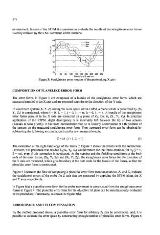
Figure 3: Straightness error motion of the probe along X axis
COMPOSITION OF PLANELIKE ERROR FORM
The error forms in Figure 3 are composed of a bundle of the straightness error forms which are
measured parallel to the X axis and are repeated stepwise to the direction of the Y axis.
In coordinate system (X, Y, Z) among the work space of the CMM, a plane which is prescribed by (X,,
Yj, Zk) is considered, where i = 0, 1, ••• 1, j = 0, 1, ••• m, k = 0, 1, ••• n. A bundle of the straightness
error forms parallel to the X axis are measured on a plane of Z o, that is, (X;, Yj, Z o). In practical
application of the STPM, slight discrepancy A is inevitably left between the tip of two sensors
(Tanaka & Sato (1986)). It has been demonstrated that iA is linearly accumulated at i-th position of
the sensors on the measured straightness error form. Then corrected error form can be obtained by
subtracting the following accumulation from the raw measured results,
Z = iA (i= 1,2,-1) (5)
The evaluation at the right-hand edge of the forms in Figure 3 shows the results with the subtraction.
However, it is presumed that residue 5z(Xi, Yj, Zo) would remain for the forms obtained for Yj (jj = 1,
2 ••• m), even if this correction is conducted. At the starting and the finishing conditions at the both
ends of the error forms, (Xo, Yj, Zo) and (Xi, Yj, Zo), the straightness error forms for the direction of
the Y axis are measured, which give boundary at the both ends for the bundle of the forms, so that the
planelike error form is constructed.
Figure 4 illustrates the flow of composing a planelike error form mentioned above. Z x and Z y indicate
the straightness errors of the probe for Z axis that are measured by applying the STPM along the X
and Y axes respectively.
In Figure 5(a) a planelike error form for the probe movement is constructed from the straightness error
forms in Figure 4. The planelike error form for the objective Al plate can be simultaneously evaluated
in the procedure, if necessary, as shown in Figure 5(b).
ERROR SPACE AND ITS COMPENSATION
By the method proposed above, a planelike error form for arbitrary Zk can be constructed, and, it is
possible to estimate the error space by constructing enough number of planelike error forms. Figure 6