Page 389 - Mechatronics for Safety, Security and Dependability in a New Era
P. 389

Ch75-I044963.fm  Page 373  Tuesday, August 1, 2006  5:58 PM
                      Page 373
                                      1, 2006
                            Tuesday, August
                                           5:58 PM
            Ch75-I044963.fm
                                                                                          373
                                                                                          373
                  Measurement  System
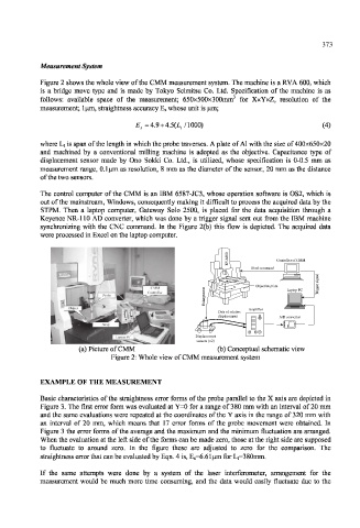
                  Figure 2 shows the whole view  of the  CMM measurement  system. The machine is a  RVA 600, which
                  is  a  bridge  move  type  and  is  made  by  Tokyo  Seimitsu  Co.  Ltd.  Specification  of  the  machine  is  as
                  follows:  available  space  of  the  measurement;  650x500x300mm  for  XxYxZ,  resolution  of  the
                  measurement;  1 urn, straightness accuracy  E s whose unit is urn;

                                          E s  = 4.9 + 4.5(i,  /1000)                     (4)

                  where L t is span of the  length  in which the probe traverses. A plate  of Al with the size of 400x650x20
                  and  machined  by  a  conventional  milling  machine  is  adopted  as  the  objective.  Capacitance  type  of
                  displacement  sensor  made  by  Ono  Sokki  Co.  Ltd.,  is  utilized,  whose  specification  is  0-0.5  mm  as
                  measurement  range,  0.1 um  as resolution,  8 mm  as the  diameter  of the  sensor,  20  mm  as the  distance
                  of the two sensors.
                  The  control  computer  of the  CMM  is an  IBM  6587-JC3, whose  operation  software  is  OS2, which  is
                  out of the mainstream,  Windows, consequently  making  it difficult  to process the acquired  data by the
                  STPM.  Then  a  laptop  computer,  Gateway  Solo  2500,  is  placed  for  the  data  acquisition  through  a
                  Keyence NR-110  AD  converter,  which  was  done by a trigger  signal  sent  out  from  the  IBM  machine
                  synchronizing  with  the  CNC  command.  In  the  Figure  2(b)  this  flow  is  depicted.  The  acquired  data
                  were processed  in Excel  on the laptop  computer.

                                                                  0
                                                                  0
                                                                  6
                                                                  A           Controller of CMM
                                                                              Controller ofCMM
                                                                  V
                                                                  R
                                                                        Feed command
                                                                                         l
                                                                                         a
                                                                                         n
                                                                                         g
                                                                                         i
                                                                                         s
                                                                Z                           r
                                                               Y         Objective plate  e
                                                            t      X                     g
                                                            n                            g
                                                            e                    Laptop PC  i
                                                            m                            r  T
                                                            e
                                                            g
                                                            r
                                                            a
                                                            l
                                                            n
                                                            E
                                                                       Amplifier
                                                               Data of relative
                                                               displacement    A/D converter
                                                         Displacement
                                                          sensors (×2)
                            (a) Picture  of CMM                (b) Conceptual  schematic view
                                    Figure 2: Whole view of CMM measurement  system
                  EXAMPLE OF THE   MEASUREMENT
                  Basic  characteristics  of the straightness  error  forms  of the  probe  parallel  to the X  axis are depicted  in
                  Figure  3. The first  error  form  was evaluated  at Y=0 for a range of 380  mm with  an interval  of 20 mm
                  and the  same evaluations  were repeated  at the coordinates  of the Y axis in the range of  320 mm with
                  an  interval  of  20  mm,  which  means  that  17  error  forms  of  the  probe  movement  were  obtained.  In
                  Figure  3 the error  forms  of the average  and the maximum  and the minimum  fluctuation  are  arranged.
                  When the evaluation  at the left  side of the forms  can be made zero, those at the right side are  supposed
                  to  fluctuate  to  around  zero.  In  the  figure  these  are  adjusted  to  zero  for  the  comparison.  The
                  straightness error that can be evaluated by Eqn. 4 is, E s=6.61um  for  Li=380mm.
                  If  the  same  attempts  were  done  by  a  system  of  the  laser  interferometer,  arrangement  for  the
                  measurement  would  be  much  more  time  consuming,  and  the  data  would  easily  fluctuate  due  to  the
   384   385   386   387   388   389   390   391   392   393   394