
Page 423 - Mechatronics for Safety, Security and Dependability in a New Era
P. 423
Ch82-I044963.fm Page 407 Saturday, July 29, 2006 7:32 AM
Page 407
7:32 AM
Ch82-I044963.fm
Saturday, July 29, 2006
407
407
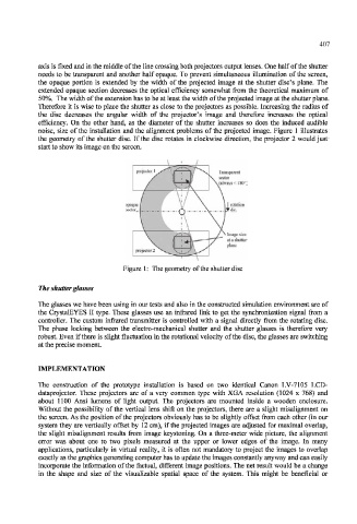
axis is fixed and in the middle of the line crossing both projectors output lenses. One half of the shutter
needs to be transparent and another half opaque. To prevent simultaneous illumination of the screen,
the opaque portion is extended by the width of the projected image at the shutter disc's plane. The
extended opaque section decreases the optical efficiency somewhat from the theoretical maximum of
50%. The width of the extension has to be at least the width of the projected image at the shutter plane.
Therefore it is wise to place the shutter as close to the projectors as possible. Increasing the radius of
the disc decreases the angular width of the projector's image and therefore increases the optical
efficiency. On the other hand, as the diameter of the shutter increases so does the induced audible
noise, size of the installation and the alignment problems of the projected image. Figure 1 illustrates
the geometry of the shutter disc. If the disc rotates in clockwise direction, the projector 2 would just
start to show its image on the screen.
Figure 1: The geometry of the shutter disc
The shutter glasses
The glasses we have been using in our tests and also in the constructed simulation environment are of
the CrystalEYES II type. These glasses use an infrared link to get the synchronization signal from a
controller. The custom infrared transmitter is controlled with a signal directly from the rotating disc.
The phase locking between the electro-mechanical shutter and the shutter glasses is therefore very
robust. Even if there is slight fluctuation in the rotational velocity of the disc, the glasses are switching
at the precise moment.
IMPLEMENTATION
The construction of the prototype installation is based on two identical Canon LV-7105 LCD-
dataprojector. These projectors are of a very common type with XGA resolution (1024 x 768) and
about 1100 Ansi lumens of light output. The projectors are mounted inside a wooden enclosure.
Without the possibility of the vertical lens shift on the projectors, there are a slight misalignment on
the screen. As the position of the projectors obviously has to be slightly offset from each other (in our
system they are vertically offset by 12 cm), if the projected images are adjusted for maximal overlap,
the slight misalignment results from image keystoning. On a three-meter wide picture, the alignment
error was about one to two pixels measured at the upper or lower edges of the image. In many
applications, particularly in virtual reality, it is often not mandatory to project the images to overlap
exactly as the graphics generating computer has to update the images constantly anyway and can easily
incorporate the information of the factual, different image positions. The net result would be a change
in the shape and size of the visualizable spatial space of the system. This might be beneficial or