
Page 428 - Mechatronics for Safety, Security and Dependability in a New Era
P. 428
Ch83-I044963.fm Page 412 Monday, August 7, 2006 11:30 AM
Ch83-I044963.fm
412
412 Page 412 Monday, August 7,2006 11:30 AM
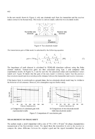
In the new model shown in Figure 4, only one electrode each from the transmitter and the receiver
makes contact to the human body. This model is conventionally called the two-electrode model.
Z d Z d Z d Z d
Z a Z a Z a Z a Z c Z c Z c Z c Z a Z a Z a Z a
Receiver side
Transmitter side Receiver side
Transmitter side
electrode
electrode electrode
electrode
Z b Z b Z b Z b
Arm
Arm
(Phantom)
(Phantom)
Figure 4: Two-electrode model
Figure 4: Two-electrode model
The transmission gain of this model is calculated by the following equation.
Z c
gain = 201og 10 Z a • "' + ^% "> ^% [dB] (2)
The impedance of each element is calculated by FEMLAB (simulator software using the finite
element method). Transmission gains are then calculated using Eqn. 2 and compared with
experimental results. Tn Figure 5a, it can be seen that the calculated values and experimental values
match well. Figure 5b shows that the gain of the new model is relatively higher than the previous
four-electrode model and does not drop as the distance between the transmitter and receiver increases.
If the human body is considered as a ground plane, the two-electrode circuit model may be similar to
the behavior of rod antennas. However, this assumption requires further study.
0 o 0 0
; ; ; ;
-10
-10 -10 -15.6 -17.7 -21.1
-10
-20 _ *- I -i ! 1 A -20 -23.5
-20
-20
-3°
-30
B „ ] -so ] ] „ B -30 -43.1
-40
-40
d [ m -40 L | [ m d -40
a r-so L | a
n -50 n i c -50 Gain 2
-50
i
-60
8 G -60 1 § G -60 -57.9 Gain 4
-60
Gain 2
-70 • -70Gai n 2 -70
-70
-70
-80 • 80 Human 1 -80 -71.8
Human 1
-80
-80 i i
-90 • 9 0 Human 2 -90 -82.1
-90
Human 2
-
-90
-100 -100
-100
-100
350
50
150
200
200
250
100
150
0 50 100 150 200 250 300 350 0 50 100 150 200 250 300 350
250
100
300
Distance of electrodes [mm]
Distance of electrodes [mm] Distance of electrodes [mm]
Distance of electrodes [mm]
a) Comparison of calculated gain with b) Comparison of two-electrode model
gain with
of two-electrode model
a) Comparison
of calculated
b) Comparison
with four-electrode model
experimental results
experimental results with four-electrode model
Figure 5: Comparison of transmission gain
MEASUREMENT OF PHASE SHIFT
The authors made a small transmitter with a size of 70 x 100 x 50 mm 3 for phase characteristics
measurement of the four-terminal circuit. The signal from the transmitter is sent to the receiver to
compare the phase difference between the original signal and the signal transmitted through the