Page 427 - Mechatronics for Safety, Security and Dependability in a New Era
P. 427

Ch83-I044963.fm  Page 411  Monday, August 7, 2006  11:30 AM
                                           11:30 AM
                            Monday, August 7,2006
            Ch83-I044963.fm
                      Page 411
                                                                                          411
                                                                                          411
                  surrounding  environment.  In order to minimize these  undesired  couplings,  signal  generator,  amplifier,
                  and  oscilloscope  are all battery-powered.  Separate  power  supplies are  used  for the transmitter  and the
                                           0 0
                                          -10
                                          -10
                                          d -20
                                          -20
                                          B
                                         3
                                          n -30
                                          -30

                                          i
                                          a
                                          G to  -40
                                          -40
                                          -50
                                          -50
                                          -60
                                          -60
                                                     15
                                                  10
                                            0 0  5 5  10  15  20  25  30  35  40
                                                       20
                                                             30
                                                                35
                                                                  40
                                                          25
                                                   Frequency
                                                          MHz
                                                   Frequency  MHz
                                  Figure 2: Comparison of transmission gain with  frequency
                  In  the  experiments,  a  human  equivalent  phantom  was  also  used.  The  conductivity  and  relative
                  permittivity  of the phantom  was adjusted  to the same value  as the human  body. Its size was 500 x 500
                  x 4500 mm  , the average size of the human  arm. Phantoms improve reproducibility  of experiments. Its
                  simple shape makes computer based calculations  easier.
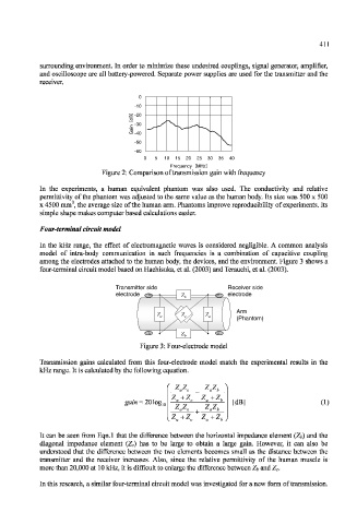
                  Four-terminal circuit model
                  In  the  kHz  range,  the  effect  of  electromagnetic  waves  is  considered  negligible.  A common  analysis
                  model  of  intra-body  communication  in  such  frequencies  is  a  combination  of  capacitive  coupling
                  among the electrodes attached  to the human  body, the devices, and the environment. Figure 3 shows a
                  four-terminal  circuit model based on Hachisuka,  et al. (2003) and Terauchi, et al. (2003).
                                     Transmitter side             Receiver side
                                                                  Receiver side
                                     Transmitter side
                                     electrode
                                                                  electrode
                                     electrode        Z b Z b Z b Z b  electrode
                                                                    Arm
                                                                    Arm
                                                Z a Z a Z a Z a  Z c Z c Z c Z c  Z a Z a Z a Z a
                                                                    (Phantom)
                                                                    (Phantom)
                                                      Z b Z b Z b Z b
                                            Figure 3: Four-electrode model
                  Transmission  gains  calculated  from  this  four-electrode  model  match  the  experimental  results  in  the
                  kHz range. It is calculated  by the following  equation.
                                                                   [dB]                   (1)
                                                            7  7
                                                     z az c
                  It can  be  seen  from  Eqn. 1 that the  difference  between  the horizontal  impedance  element  (Zj)  and the
                  diagonal  impedance  element  (Z c)  has  to  be  large  to  obtain  a  large  gain.  However,  it  can  also  be
                  understood  that  the  difference  between  the  two  elements  becomes  small  as  the  distance  between  the
                  transmitter  and  the  receiver  increases.  Also,  since  the  relative  permittivity  of  the  human  muscle  is
                  more than 20,000 at  10 kHz,  it is difficult  to enlarge the difference  between Zj and Z c.
                  In this research, a similar four-terminal  circuit model  was investigated  for  a new form  of transmission.
   422   423   424   425   426   427   428   429   430   431   432