
Page 429 - Mechatronics for Safety, Security and Dependability in a New Era
P. 429
Ch83-I044963.fm Page 413 Monday, August 7, 2006 11:30 AM
Monday, August 7,2006
11:30 AM
Ch83-I044963.fm
Page 413
413
413
phantom. To avoid unnecessary electrical coupling, optical fiber is used to send the synchronization
signals. The distance between the transmitter and the receiver is 300 mm.
1.4 180
;
1.2 135
i
] 1 ] 90
. 10AS
10AS
u g S10AS
. e 45
a 0.8 d
10BS
[ 10BS
[ 10BS
r
e e 0
w 0.6 10CS s a S10CS
10CS
o h -45
P 0.4 10DS P S10DS
10DS
-90
0.2 -135
1
0 -180
0 90 180 270 360 0 90 180 270 360
90
180
270
360
180
270
360
Angle [deg]
Angle [deg] Angle [deg]
Angle [deg]
a) Comparison of signal power with b) Comparison of phase shift with
with
of signal power with
b) Comparison
of phase shift
a) Comparison
alignments
electrode
electrode alignments
electrode alignments electrode alignments
Transmitter
Transmitter
Transmitter Transmitter
10AS
• • 10AS • • 10CS • •
10CS
10BS
10DS
D • 10BS • S 10DS •
0
of electrodes
c) Alignments of electrodes
c) Alignments
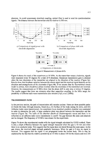
Figure 6: Measurement of phase shifts
Figure 6 shows the result of the experiment at 10 MHz. As the transmitter rotates clockwise, signals
were measured every 45 degrees for a total of 8 directions. Maximum transmission gain is attained
when the two electrodes of the transmitter are aligned to the direction of the receiver (Figure 6a).
Results show that the phase variation between the source signal and the received signal depends on the
direction and arrangements of the electrodes (Figure 6b). If we assume that the four-terminal circuit
model is correct, there should be a phase reversal when the electrodes of the transmitter are reversed.
However, the measurements at 10 MHz show that the phase shift is only plus or minus 45 degrees.
The results suggest that there are elements other than capacitive coupling. In the MHz range, the
possibility of airborne radio wave transmission also remains (Fujii, et al. (2004)).
TRANSMISSION PATH
In the previous section, the path of transmission still remains unclear. There are three possible paths:
(i) Inside the body (through muscles, blood etc.), (ii) Surface of the body (along the skin), and (iii)
Airborne (radio wave transmission). An experiment in an electrical anechoic chamber was conducted
in order to determine the path. A large conductor plate was placed between the transmitter and the
receiver (Figure 7a). The walls of the chamber absorb all electromagnetic waves and there is no
reflection so all airborne radio wave transmission is cutoff. The gap between the plate and phantom
can be changed. The frequency of 10 MHz was chosen for the experiment.
Figure 7b shows the experimental results with the signal strength calculated by FDTD method. There
is only a slight difference between the signal strength measured when the gap is 10 mm and when
there is no conductor plate. This suggests that the signal does not travel through the open space. As the
gap closes, the received signal strength gradually decreases. When the gap is 0 mm, no signal is
received. This suggests that the signal is not propagated inside the human body. This is may be
explained by the fact that the relative permittivity at 10 MHz is about 150 for the muscle and over 250