
Page 67 - Mechatronics for Safety, Security and Dependability in a New Era
P. 67
Ch11-I044963.fm Page 51 Tuesday, August 1, 2006 8:51 PM
1, 2006
Tuesday, August
Page 51
8:51PM
Ch11-I044963.fm
51 51
Wheel torque T
Wheel torque T
sin a.
Wheel radius
R=D/2
§0.6
(0< α <π /2)
αα F1 Moving | 0.4 -//=0.37(for examplej^^ P
direction
o
Load at rear
F5 Run over y^
wheels β Wg
F1' .N 0.2
Friction force \ Vs Enable to drive rollers I
F5' μ β Wg E
0.0
V Roller I
Roller I
IV II 0.0 0.2 0.4 0.6 0.8
III
Contact angle of wheels a [rad]
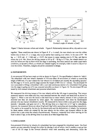
Figure 7: Statics between rollers and wheels Figure 8: Relationship between drive, slip and run over
together. These conditions are shown in Figure 8. If a is small, the rear wheels ran over the rollers
before slip on them. If a is large, slip occurs earlier than running over rollers. In the case of W = 90
kg, a = 0.33 rad, /? = 0.66 and ju =0.37, the torque to cause running over is 53 Nm, and that to
cause slip is 61 Nm. Since the driving torque to lift up W = 90 kg is 3.3 Nm, the wheels doesn't ran
over the rollers nor slip on them while the stage is ascending. But these analysis are under quasi-static
conditions, so dynamic effects, as wheels are rotated roughly for example, make it easier to slip or run
over the rollers. Therefore, margins should be considered in design.
6. EXPERIMENTS
A non-powered lift has been made on trial as shown in Figure 9. The specification is shown in Table 1.
The wheelchair with rear wheel's diameter of 570 mm takes 18 revolutions of wheels to ascend the
height of 600 mm. If a user rotates the rear wheels 0.3 revolution per second, the ascending speed of
the lift stage is 10 mm/s, and the stage ascends the height of 600 mm in 1 minute. The developed lift
was succeeded to lifting a wheelchair with a user and continuous motion of a wheelchair from going
into the stage to going out of it was executed smoothly as shown in Figure 10. The developed lift was
tested by both manual wheelchairs and powered wheelchairs.
We measured the driving torque of the rear wheels while the lift stage is ascending. The torque
measured sensors were made and they were attached between the wheels and hand rims as shown in
Figure 11. When a user acts the forces at the hand rims to rotate wheels, sensors of thin cylinders are
distorted and they are measured by strain gages. The measurements were done by handicapped
persons who use manual wheelchairs usually. We measured the forces while a user goes into the stage,
ascends / descends, and goes out of it. The driving force at a hand rim is 0.7 kgf in calculation,
however, the measured forces are about 8 kgf and 6 kgf while ascending and descending respectively.
This seems to be caused by the loss by the transmission and the deformation of wheels, the resistance
by front casters, which are rotated by the rear wheels via the rollers, and dynamic effects by the
motion that a user rotate the wheels discontinuously. However, measured force when running on flat
floor is about 5 kgf, so the driving force is as same as or little larger than that.
7. CONCLUSION
Non-powered lift driven by wheels of a wheelchair has been proposed for wheelchair users. The front
casters can pass smoothly through the rollers by placing 4 sets of rollers. And it enables a user go into
/ out of the lift stage in the forward direction when both ascending and descending. Since the