
Page 64 - Mechatronics for Safety, Security and Dependability in a New Era
P. 64
Ch11-I044963.fm Page 48 Tuesday, August 1, 2006 8:51 PM
Ch11-I044963.fm
48 48 Page 48 Tuesday, August 1, 2006 8:51PM
Worn
gear/wheel of a
wheelchair
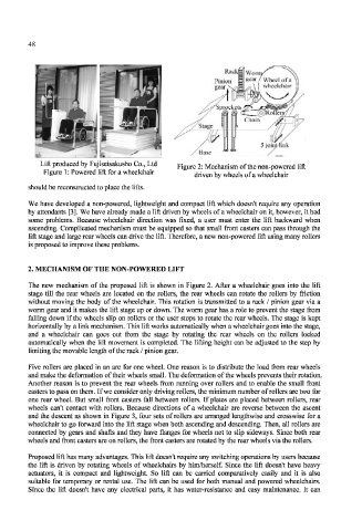
Lift produced by Fujiseisakusho Co., Ltd Figure 2: Mechanism of the non-powered lift
Figure 1: Powered lift for a wheelchair
driven by wheels of a wheelchair
should be reconstructed to place the lifts.
We have developed a non-powered, lightweight and compact lift which doesn't require any operation
by attendants [3]. We have already made a lift driven by wheels of a wheelchair on it, however, it had
some problems. Because wheelchair direction was fixed, a user must enter the lift backward when
ascending. Complicated mechanism must be equipped so that small front casters can pass through the
lift stage and large rear wheels can drive the lift. Therefore, a new non-powered lift using many rollers
is proposed to improve these problems.
2. MECHANISM OF THE NON-POWERED LIFT
The new mechanism of the proposed lift is shown in Figure 2. After a wheelchair goes into the lift
stage till the rear wheels are located on the rollers, the rear wheels can rotate the rollers by friction
without moving the body of the wheelchair. This rotation is transmitted to a rack / pinion gear via a
worm gear and it makes the lift stage up or down. The worm gear has a role to prevent the stage from
falling down if the wheels slip on rollers or the user stops to rotate the rear wheels. The stage is kept
horizontally by a link mechanism. This lift works automatically when a wheelchair goes into the stage,
and a wheelchair can goes out from the stage by rotating the rear wheels on the rollers locked
automatically when the lift movement is completed. The lifting height can be adjusted to the step by
limiting the movable length of the rack / pinion gear.
Five rollers are placed in an arc for one wheel. One reason is to distribute the load from rear wheels
and make the deformation of their wheels small. The deformation of the wheels prevents their rotation.
Another reason is to prevent the rear wheels from running over rollers and to enable the small front
casters to pass on them. If we consider only driving rollers, the minimum number of rollers are two for
one rear wheel. But small front casters fall between rollers. If plates are placed between rollers, rear
wheels can't contact with rollers. Because directions of a wheelchair are reverse between the ascent
and the descent as shown in Figure 3, four sets of rollers are arranged lengthwise and crosswise for a
wheelchair to go forward into the lift stage when both ascending and descending. Then, all rollers are
connected by gears and shafts and they have flanges for wheels not to slip sideways. Since both rear
wheels and front casters are on rollers, the front casters are rotated by the rear wheels via the rollers.
Proposed lift has many advantages. This lift doesn't require any switching operations by users because
the lift is driven by rotating wheels of wheelchairs by him/herself. Since the lift doesn't have heavy
actuators, it is compact and lightweight. So lift can be carried comparatively easily and it is also
suitable for temporary or rental use. The lift can be used for both manual and powered wheelchairs.
Since the lift doesn't have any electrical parts, it has water-resistance and easy maintenance. Tt can