
Page 66 - Mechatronics for Safety, Security and Dependability in a New Era
P. 66
Ch11-I044963.fm Page 50 Tuesday, August 1, 2006 8:51 PM
Ch11-I044963.fm
50
50 Page 50 Tuesday, August 1, 2006 8:51PM
Pinion gear Diameter:D
Diameter:D
Pinion gear
diameter:Dp Rotation angle:θ
Rotation angle:θ
diameter:Dp
Velocity:v
Reduce Velocity:v
Angular velocity:
Ratio:i Angular velocity:ω ω
load:Wg
Lifting
Lifting load:Wg /
Torque:
Torque:T T
Driving torque
Load of
Load of Without assist mechanism
stage:W'g Roller diameter:d
stage: W'g
Roller diameter:d
g
n :y
Number of gas springs:n
Number of gas springs:n di ht
Assist force:FG
Assist force:FG n c g e i — • — _ — —
A h s e : —- —
Expansion at
Expansion at
δ lowest position 0 100 200 300 400 500 600
lowest position
Ascending height y [mm]
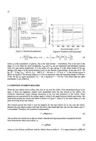
Figure 5: Mechanical parameters Figure 6: Variation of driving torque
* D*i Ftnax — Fmin
(Wg + W'g-Fc) Fc = (2)
where g is the acceleration of gravity, Wg is the load (human + wheelchair), W'g is the load of the
stage, Fa is the force by assist mechanism, F and F i are the maximum and minimum reaction
max m n
force of a gas spring respectively, S is the stroke of a gas spring, 5 is the initial stroke of the gas
springs (The stage is at the lowest position) and n is the number of gas springs. In the case of W — 90
kg, W = 75 kg, F = 654 N, F = 490 N, S = 340 mm, S = 27 mm, « = 4, the driving torque is
max min
shown in Figure 6. The driving torque is 3.3 Nm at maximum when the ascending height is 570 mm.
If the lift has no assist mechanism (Fg = 0), it becomes T = 7.8 Nm. This shows that the assist
mechanism is very effective.
5. CONDITION TO DRIVE ROLLERS
When the rear wheels drives rollers, they slip or run over the rollers if the transmitted torque is too
large. If these are happened, rotation can't transmitted from the rear wheels to the rollers. The
maximum transmitted torque changes according to the size and placement of the rollers. These
parameters are represented by the contact angle a, which is the angle between wheels and rollers. The
relationship around the wheels and rollers is shown in Figure 7, where R is the wheel radius, fS is the
ratio of the load at the rear wheels.
The moment around the roller T must be negative for the rear wheels not to run over the rollers.
Because the rear wheels contact with only the roller I the instant that they run over the rollers, only F\
is considered. Therefore, this condition is expressed by
T<pWgRsma (3)
The condition for wheels not to slip on rollers is that the driving torque doesn't exceed the friction
force between the wheels and rollers, i.e.
(4)
where // is the friction coefficient, and the friction force at rollers 1 ~ V is approximated to fifiWg all