
Page 70 - Mechatronics for Safety, Security and Dependability in a New Era
P. 70
Ch12-I044963.fm Page 54 Tuesday, August 1, 2006 9:08 PM
Ch12-I044963.fm
54 54 Page 54 Tuesday, August 1, 2006 9:08 PM
12
] N I
a
l =0~0.85[m] a Sp Sp r a r r l i i n n g g F l [ 10 F l F
l =0~0.85[m]
i
Spiral
Spring
Sp Spring
c c e c 8 J
r r
L L o f 6
e 4
P2
P2 l i
P1
P1
og
D
Dog’s lead b b a a a (Reduction n s n
’
ead
l
s
c
u
e
d
(R Reduction
o
t
i
/1
ratio 1/10) 0 ) e 2
ti
1
o
ra ratio 1/10)
φ : ± π /2[rad] Potentiometer T 0
P Potentiometer
o
m
e
ter
o
ten
t
i
ccw >0
cc w > 0 0 0 0.2 0.4 0.6 0.8
0.6
0.2
0.4
0.8
Se r v i ce Dog g
D
e
Servic
Service Dog
o
Towing length l [m]
Towing length l [m]
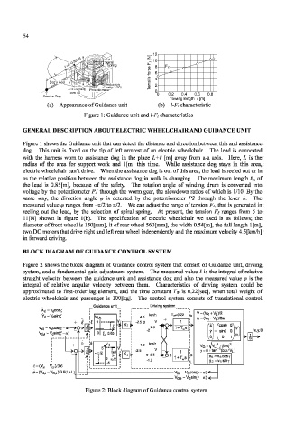
(a) Appearance of Guidance unit (b) l-Fi characteristic
Figure 1: Guidance unit and 1-Fi characteristics
GENERAL DESCRIPTION ABOUT ELECTRIC WHEELCHAIR AND GUIDANCE UNIT
Figure 1 shows the Guidance unit that can detect the distance and direction between this and assistance
dog. This unit is fixed on the tip of left armrest of an electric wheelchair. The lead is connected
with the harness worn to assistance dog in the place L+C [m] away from a-a axis. Here, L is the
radius of the area for support work and 1 [m] this time. While assistance dog stays in this area,
electric wheelchair can't drive. When the assistance dog is out of this area, the lead is reeled out or in
as the relative position between the assistance dog in walk is changing. The maximum length t m of
the lead is 0.85[m], because of the safety. The rotation angle of winding drum is converted into
voltage by the potentiometer PI through the worm gear, the slowdown ratios of which is 1/10. By the
same way, the direction angle <p is detected by the potentiometer P2 through the lever b. The
measured value q> ranges from —nil to TT/2. We can adjust the range of tension Ft, that is generated in
reeling out the lead, by the selection of spiral spring. At present, the tension Ft ranges from 5 to
11[N] shown in figure l(b). The specification of electric wheelchair we used is as follows; the
diameter of front wheel is 150[mm], it of rear wheel 560[mm], the width 0.54[m], the full length 1 [m],
two DC motors that drive right and left rear wheel independently and the maximum velocity 4.5[km/h]
in forward driving.
BLOCK DIAGRAM OE GUIDANCE CONTROL SYSTEM
Figure 2 shows the block diagram of Guidance control system that consist of Guidance unit, driving
system, and a fundamental gain adjustment system. The measured value I is the integral of relative
straight velocity between the guidance unit and assistance dog and also the measured value <p is the
integral of relative angular velocity between them. Characteristics of driving system could be
approximated to first-order lag element, and the time constant T w is 0.22[sec], when total weight of
electric wheelchair and passenger is 100[kg]. The control system consists of translational control
Guidance unit Driving system
X d = V dcosf
V = ( V R + V L ) / 2
Y d =V d sinf
V( w = (V R -V L )/2a
5
cose °1
sin8 o (x,y,e)
•>.
85
0 E d I
0
.Vtf
5'
77 12 (bu)/V L)
- rad
J 0 i l l
-5
-V G; =V G cosO-a)
Figure 2: Block diagram of Guidance control system