
Page 69 - Membranes for Industrial Wastewater Recovery and Re-Use
P. 69
Membrane technology 49
much smaller than the cross-flow velocity, which is normally the case in cross-
flow membrane systems. However, all membrane elements include a spacer that
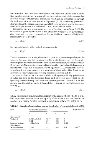
provides a degree of turbulence promotion, which can be accounted for through
the inclusion of additional terms in Equation (2.16) containing parameters
characterising the spacer. An example, which incorporates a term in the spacer
meshwidthparameter rn (Chiolleetal., 1978), isincludedinTable2.11.
Expressions can also be presented in terms of the shear rate y (Table 2.12). The
shear rate is given by the ratio of the cross-flow velocity U to the hydraulic
dimension and is geometry dependent. For parallel flow channels of height h its
maximum value is given by:
(2.19)
For tubes of diameter d the equivalent expression is:
yo = 8U/d (2.20)
The impact of concentration polarisation on process operation depends upon the
process. For pressure-driven processes the main impacts are on feedwater
osmotic pressure and scalant levels, since both will increase by a factor of up to p/
(1 - 0) overall. The osmotic pressure effect raises the required applied pressure to
maintain the target flux in accordance with Equation (2.7), whereas the increase
in scalant levels may produce precipitation of these salts. This demands an
appropriate choice of process operating conditions (Section 2.4.2).
In the case of extractive processes, and electrodialysis specifically, polarisation
depletes the ions in the boundary layer and places an upper limit on the
operating current density, and so on the operating current (Section 2.4.2). The
current density attained under this condition is known as the limiting current
density Ilim:
I1im N 2kCF (2.21)
where k is the mass transfer coefficient given by Equations (2.1 5)-(2.18), C is the
bulk equivalent concentration (in eq mW3) of the diluate (i.e. the desalinated
product) and F is the Faraday constant, which takes a value of 96 500 C eq-'.
Table 2.11 Examples of empirical and semi-empirical values of constants in Equation (2.16)
Flow Characteristic constants Additional term
a b C n
Open channel
Turbulent 0.023 or0.065 0.875 0.25 0
0.04 0.75 0.33 0
Laminar (LCvEque) 1.62 or 1.86 0.33 0.33 0.33
Filled channel
Intermediate flow 1.065 0.5 0.33 0.5 (1/6m)O