
Page 73 - Membranes for Industrial Wastewater Recovery and Re-Use
P. 73
Membrane technology 5 3
In reverse osmosis and nanofiltration even the largest membrane elements
cannot normally achieve a recovery of much more than 20%, and the onset of
concentration polarisation and the scaling this produces normally limits the
conversion to well below this figure. It is therefore normal for them to be placed
in series, with the retentate stream from one element being passed on to the feed
stream of the next (Fig. 2.19). As many as eight or nine elements may be placed
in a single module, and the resultant retentate flow exiting the module is then
given by (fromEquation (2.3)):
QR = Q( 1 - 0)" (2.22)
where Q is the feed flow rate, 0 the conversion per element and n the number of
elements per module.
As the water flows along the length of a module the overall conversion is
increased until there may come a point at which the element is running well
below capacity. For example if, in Fig. 2.19, the conversion is 16% per element
then the flow in stream 8 will be (1 - N 0.5 that of the feed. Under such
3 5 9
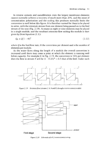
Figure 2.19 Retentatejow (streams 2,4,6 and 8) through a reverse osmosis module
u
product
First stage Second stage
Figure 2.20 Schematic of a 4:2 reverse osmosis array