
Page 113 - Methods For Monitoring And Diagnosing The Efficiency Of Catalytic Converters A Patent - oriented Survey
P. 113
Toyota Motor Co. Ltd. 95
b) sensor deteriorated: Both L, and A, are small regardless of the deterioration
of the catalytic converter (figs. 45c,d and figs. 46.c,d)
Downstream oxygen sensor:
a) catalytic converter not deteriorated: 1) Length L2 is small regardless of the
deterioration of the downstream sensor (figs. 45a-d) 2) Area A2 is large for
non-deteriorated oxygen sensor (figs. 45%~) and is medium for deteriorated
downstream oxygen sensor (figs. 45b,d)
b) catalytic converter deteriorated: 1) Both L2 and A2 are large for non-
deteriorated downstream oxygen sensor (figs. 46a,c) 2) L2 is medium and
A2 is small for deteriorated downstream oxygen sensor (figs. 46b,d)
The ratios of lengths and areas are calculated and shown to the two right columns of fig. 45
and fig. 46. The combination of these ratios gives an accurate estimation of the condition of
the catalytic converter.
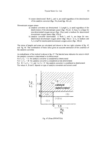
An embodiment of the method is shown in fig. 47. The hatched area indicates the area in which
the catalytic converter is determined to be deteriorated.
For L2/ L, > A the catalytic converter is considered as deteriorated.
For Lz/ Lt < B the catalytic converter is considered as non-deteriorated.
For B < L2/ L1 < A and AZ/ AI < C the catalytic converter is considered as deteriorated.
The values A, B and C depend on type of catalytic converters and sensors used.
Fig. 47 (from EP0547326)