
Page 232 - Methods For Monitoring And Diagnosing The Efficiency Of Catalytic Converters A Patent - oriented Survey
P. 232
214 Methods for Monitoring and Diagnosing the Eficiency of Catalytic Converters
8) judging a deterioration of the catalytic converter by calculating a ratio between both number
signals. The advantage is that a misjudgment of the deterioration is avoided by eliminating
an amplitude output disturbance from the downstream aidfuel ratio sensor due to a
fluctuation of the engine operating conditions
rich T
I umer slice lower slice I
upstream
sensor voltage
I
downstream
sensor voltage
time elapsed
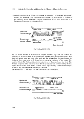
Fig. 94 (from US5337556)
Fig. 94 shows the case of a deteriorated catalytic converter. Figs. 94a and b show the
variations of the upstream and downstream sensor output voltages during testing time T. The
first and second upper and lower slice levels are also indicated on the same figures. As
indicated above these slice levels depend on the operating conditions of the engine. The
number of times that the downstream sensor output is cut by the second upper and lower slice
levels is compared to the number of times that the upstream sensor output is cut by the first
upper and lower slice levels. In this case the ratio is high indicating a deteriorated catalytic
converter. low indicating an efficient catalytic converter.
In the case of fig. 95 this ratio is very low indicating an eficient converter.
rich T
, upper slice lower slice ~
upstream
sensor voltage
downstream
sensor voltage
time elapsed
Fig. 95 (from US5337556)
214