
Page 237 - Methods For Monitoring And Diagnosing The Efficiency Of Catalytic Converters A Patent - oriented Survey
P. 237
Other Methods 219
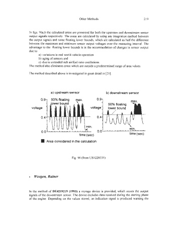
In figs. 96a,b the calculated areas are presented for both the upstream and downstream sensor
output signals respectively. The areas are calculated by using any integration method between
the output signals and some floating lower bounds, which are calculated as half the difference
between the maximum and minimum sensor output voltages over the measuring interval. The
advantage to the floating lower bounds is in the accommodation of changes in sensor output
due to:
a) variations in real world vehicle operation
b) aging of sensors and
c) due to extended rich aidfuel ratio oscillations.
The method also eliminates areas which are outside a predetermined range of area values.
The method described above is investigated in great detail in [21].
a) upstream sensor b) downstream sensor
50% floating Fax. 0.97 Max.
i
voltage
*,
Oa4I , mi!., , , ,
0.0
time (sec) time (see)
Area considered in the calculation
Fig. 96 (fiom US5228335)
Weegen, Rainer
In the method of DE4219219 (1993) a storage device is provided, which stores the output
signals of the downstream sensor, The device excludes data received during the starting phase
of the engine. Depending on the values stored, an indication signal is produced warning the