
Page 302 - Methods For Monitoring And Diagnosing The Efficiency Of Catalytic Converters A Patent - oriented Survey
P. 302
284 Methods for Monitoring and Diagnosing the Efficiency of Catalytic Converters
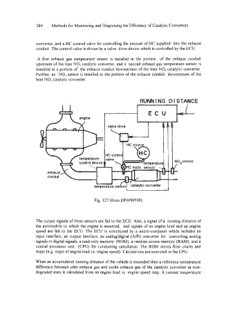
converter, and a HC control valve for controlling the amount of HC supplied into the exhaust
conduit. The control valve is driven by a valve drive device which is controlled by the ECU.
A first exhaust gas temperature sensor is installed in the portion of the exhaust conduit
upstream of the lean NO, catalytic converter, and a second exhaust gas temperature sensor is
installed in a portion of the exhaust conduit downstream of the lean NOx catalytic converter.
Further, an NO, sensor is installed in the portion of the exhaust conduit downstream of the
lean NO, catalytic converter.
Fig. 127 (from EP0498598)
The output signals of these sensors are fed to the ECU. Also, a signal of a running distance of
the automobile to which the engine is mounted, and signals of an engine load and an engine
speed are fed to the ECU. The ECU is constituted by a micro-computer which includes an
input interface, an output interface, an analoddigital (ND) converter for converting analog
signals to digital signals, a read-only memory (ROM), a random access memory (RAM), and a
central processor unit (CPU) for conducting calculation. The ROM stores flow charts and
maps (e.g. maps of engine load vs. engine speed). Calculations are executed in the CPU.
When an accumulated running distance of the vehicle is exceeded then a reference temperature
difference between inlet exhaust gas and outlet exhaust gas of the catalytic converter at non-
degraded state is calculated from an engine load vs. engine speed map. A current temperature