
Page 69 - Methods For Monitoring And Diagnosing The Efficiency Of Catalytic Converters A Patent - oriented Survey
P. 69
Robert Bosch GmbH. 51
Q,,, : the volume of air introduced to the engine during the time interval At,
h
RPM
A1
1,05
0,95
A2
1,05
0,98
0,95 TIME
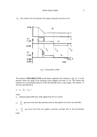
Fig. 2 1 (from DE4 1 12480)
The method of DE4128823 (1993) can be better explained with reference to fig. 22. To is the
moment where the signal of the upstream probe changes from lean to rich. The broken line
indicates the corresponding behavior of the downstream sensor output signal. The symbol t, is
the time span defined as
where
t,,, measured phase shift time of the signals from the two probes
:
t =A: travel time from the upstream probe to the catalytic converter upstream face
gas
Q*,
tc;A.: k2 : gas travel time from the catalytic converter upstream face to the downstream
=
Q-,
probe