
Page 89 - Methods For Monitoring And Diagnosing The Efficiency Of Catalytic Converters A Patent - oriented Survey
P. 89
Ford Motor Co. - Ford France SA - Ford Werke AG - Ford Motor Co. Ltd. 71
In EP0521641 (1993) and US5313791 (1994) thefeedhack pin of the feedback loop control
is the parameter that defines the exhaustion of a catalytic converter. The rate at which the
controller system increases or decreases the engine airhe1 ratio for a step change in the
downstream HEGO sensor output is defined as the pin of the post-catalytic converter air/fbel
feedback system. The engine is operated under closed-loop control with the downstream
HEGO probe controlling the air/hel ratio. Three embodiments of this method are presented:
1) The gain of the downstream air/hel feedback loop is set at a low value during test. Low
value means that when the catalytic converter conversion efficiency is high enough then no
definite limit cycle oscillation is produced. Any degradation of the catalytic converter is
detected by looking for a decrease in the amplitude of the HEGO sensor output fluctuations
compared to the value measured with a good catalytic converter. Temperature corrections
to the HEGO control signal may also be applied.
2) The gain of the feedback loop is automatically adjusted to maintain the amplitude of the
HEGO sensor output at a particular value. As the catalytic converter conversion efficiency
decreases, the gain would automatically increase. When the gain exceeds some preset level
then the catalytic converter is considered as exhausted.
3) The feedback gain is increased from an initial low value until it is high enough to produce a
relatively clean limit cycle oscillation. At that point, the gain is held constant and the limit
cycle frequency is measured. A low gain is used initially to prevent overdriving the catalytic
converter, which could result in a multiplicity of limit cycle frequencies. Thus, indication of
catalytic converter degradation is based on a combination of the feedback gain required to
produce a limit cycle oscillation and the value of the limit cycle frequency.
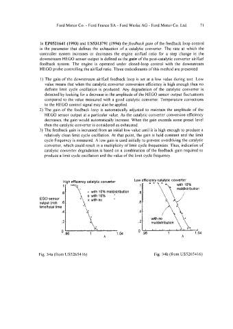
': . - rr '(,,,\yution
.a a with 10% maldistribution 1:
1 o with 10%
EGO sensor "! x wth no " z
output (rich .6 - 1 .6 c
timehotal time "\ A "I
.4 - . ,\, .4 - i
.2 - .2 z;iribution/i
- , , , ,
Fig. 34a (from US52654 16) Fig. 34b (from US5265416)