
Page 229 -
P. 229
220 6 Answers, Hints and Solutions
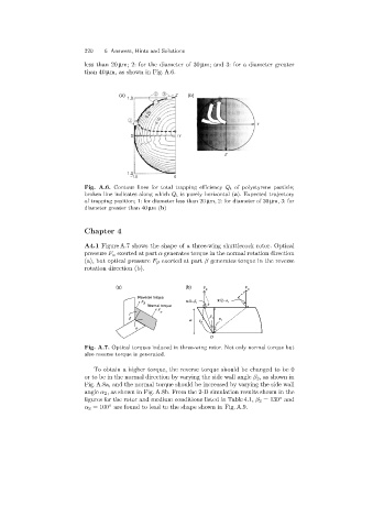
less than 20 µm; 2: for the diameter of 30 µm; and 3: for a diameter greater
than 40 µm, as shown in Fig. A.6.
(a) - Z (b)
1.0
0.20
0.10 Y
0
0 +Y
Z
-1.0
-1.0 0
Fig. A.6. Contour lines for total trapping efficiency Q t of polystyrene particle;
broken line indicates along which Q t is purely horizontal (a). Expected trajectory
of trapping position; 1: for diameter less than 20 µm, 2: for diameter of 30 µm, 3: for
diameter greater than 40 µm(b)
Chapter 4
A4.1 Figure A.7 shows the shape of a three-wing shuttlecock rotor. Optical
pressure F α exerted at part α generates torque in the normal rotation direction
(a), but optical pressure F β exerted at part β generates torque in the reverse
rotation direction (b).
(a) (b) F F
b a
Reverse torque
F p /2-b p /2-a 1
b 1
Normal torque
F
a
b b 1 a
w r 2 1
a
O
Fig. A.7. Optical torques induced in three-wing rotor. Not only normal torque but
also reverse torque is generated.
To obtain a higher torque, the reverse torque should be changed to be 0
or to be in the normal direction by varyingthe side wall angle β 2 , as shown in
Fig. A.8a, and the normal torque should be increased by varying the side wall
angle α 2 , as shown in Fig. A.8b. From the 2-D simulation results shown in the
◦
figures for the rotor and medium conditions listed in Table 4.1, β 2 = 130 and
◦
α 2 = 100 are found to lead to the shape shown in Fig. A.9.