
Page 93 -
P. 93
3.1 Background 83
Ashkin and his coworkers at ATT Bell Laboratory demonstrated a trap-
pingphenomenon due to the optical pressure force generated by counterpropa-
gating laser beams in the early 1970s [3.2]. There is a great deal of theoretical
and experimental knowledge and technology in this field [3.3, 3.4]. Here, a
single-beam gradient-force optical trap is applied in various scientific and en-
gineeringfields includingbiology [3.3,3.5], microchemistry [3.6], physics [3.7],
micromechanics [3.8]. It consists of a single beam that is strongly focused by
a high-numerical-aperture (high-NA) objective lens of a microscope.
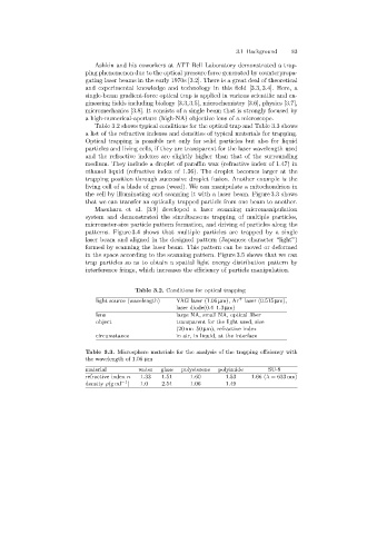
Table 3.2 shows typical conditions for the optical trap and Table 3.3 shows
a list of the refractive indexes and densities of typical materials for trapping.
Optical trappingis possible not only for solid particles but also for liquid
particles and livingcells, if they are transparent for the laser wavelength used
and the refractive indexes are slightly higher than that of the surrounding
medium. They include a droplet of paraffin wax (refractive index of 1.47) in
ethanol liquid (refractive index of 1.36). The droplet becomes larger at the
trappingposition through successive droplet fusion. Another example is the
livingcell of a blade of grass (weed). We can manipulate a mitochondrion in
the cell by illuminatingand scanningit with a laser beam. Figure 3.3 shows
that we can transfer an optically trapped particle from one beam to another.
Masuhara et al. [3.9] developed a laser scanningmicromanipulation
system and demonstrated the simultaneous trappingof multiple particles,
micrometer-size particle pattern formation, and drivingof particles alongthe
patterns. Figure 3.4 shows that multiple particles are trapped by a single
laser beam and aligned in the designed pattern (Japanese character “light”)
formed by scanningthe laser beam. This pattern can be moved or deformed
in the space accordingto the scanningpattern. Figure 3.5 shows that we can
trap particles so as to obtain a spatial light energy distribution pattern by
interference fringe, which increases the efficiency of particle manipulation.
Table 3.2. Conditions for optical trapping
light source (wavelength)YAG laser (1.06 µm), Ar + laser (0.515 µm),
laser diode(0.4–1.3 µm)
lens large NA, small NA, optical fiber
object transparent for the light used, size
(20 nm–50 µm), refractive index
circumstance in air, in liquid, at the interface
Table 3.3. Microsphere materials for the analysis of the trapping efficiency with
the wavelength of 1.06 µm
material water glass polysterene polyimide SU-8
refractive index n 1.33 1.51 1.60 1.53 1.66 (λ = 633 nm)
density ρ(g ml −1 )1.0 2.54 1.06 1.49 –