
Page 98 -
P. 98
88 3 Optical Tweezers
(a) Laser (b) Laser
b a b F a
F at at
Objective
f f
F a
F a F F b Microsphere F O
O F b
F ao F ao
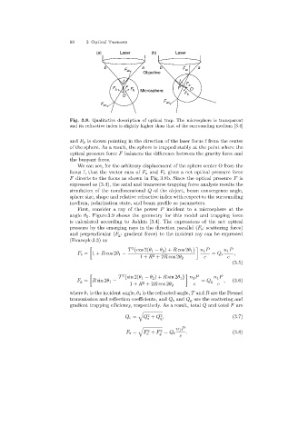
Fig. 3.8. Qualitative description of optical trap. The microsphere is transparent
and its refractive index is slightly higher than that of the surrounding medium [3.4]
and F b is shown pointingin the direction of the laser focus f from the center
of the sphere. As a result, the sphere is trapped stably at the point where the
optical pressure force F balances the difference between the gravity force and
the buoyant force.
We can see, for the arbitrary displacement of the sphere center O from the
focus f, that the vector sum of F a and F b gives a net optical pressure force
F directs to the focus as shown in Fig. 3.8b. Since the optical pressure F is
expressed as (3.4), the axial and transverse trappingforce analysis results the
simulation of the nondimensional Q of the object, beam convergence angle,
sphere size, shape and relative refractive index with respect to the surrounding
medium, polarization state, and beam profile as parameters.
First, consider a ray of the power P incident to a microsphere at the
angle θ 1 . Figure 3.9 shows the geometry for this model and trapping force
is calculated accordingto Ashkin [3.4]. The expressions of the net optical
pressure by the emerging rays in the direction parallel (F s : scatteringforce)
and perpendicular (F g : gradient force) to the incident ray can be expressed
(Example 3.3) as
T {cos 2(θ 1 − θ 2 )+ R cos 2θ 1 } n 1 P n 1 P
2
F s = 1+ R cos 2θ 1 − 2 = Q s ,
1+ R +2R cos 2θ 2 c c
(3.5)
2
T {sin 2(θ 1 − θ 2 )+ R sin 2θ 1 } n 1 P n 1 P
F g = R sin 2θ 1 − = Q g , (3.6)
2
1+ R +2R cos 2θ 2 c c
where θ 1 is the incident angle, θ 2 is the refracted angle, T and R are the Fresnel
transmission and reflection coefficients, and Q s and Q g are the scatteringand
gradient trapping efficiency, respectively. As a result, total Q and total F are
2
2
Q t = Q + Q , (3.7)
s g
n 1 P
2
2
F t = F + F = Q t . (3.8)
s
g
c