
Page 95 -
P. 95
3.2 Theoretical Analysis 85
Details of the analytical and experimental studies of the single-beam op-
tical trap are presented in the followingsections.
3.2 Theoretical Analysis
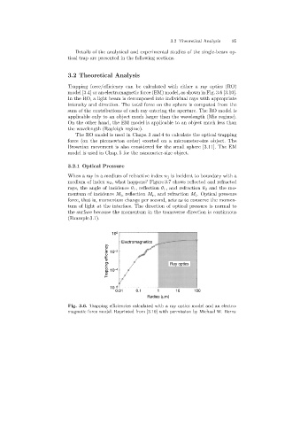
Trappingforce/efficiency can be calculated with either a ray optics (RO)
model [3.4] or an electromagnetic force (EM) model, as shown in Fig. 3.6 [3.10].
In the RO, a light beam is decomposed into individual rays with appropriate
intensity and direction. The total force on the sphere is computed from the
sum of the contributions of each ray enteringthe aperture. The RO model is
applicable only to an object much larger than the wavelength (Mie regime).
On the other hand, the EM model is applicable to an object much less than
the wavelength (Rayleigh regime).
The RO model is used in Chaps. 3 and 4 to calculate the optical trapping
force (on the piconewton order) exerted on a micrometer-size object. The
Brownian movement is also considered for the small sphere [3.11]. The EM
model is used in Chap. 5 for the nanometer-size object.
3.2.1 Optical Pressure
When a ray in a medium of refractive index n 1 is incident to boundary with a
medium of index n 2 , what happens? Figure 3.7 shows reflected and refracted
rays, the angle of incidence θ 1 , reflection θ 1 , and refraction θ 2 and the mo-
mentum of incidence M i , reflection M r , and refraction M t . Optical pressure
force, that is, momentum change per second, acts as to conserve the momen-
tum of light at the interface. The direction of optical pressure is normal to
the surface because the momentum in the transverse direction is continuous
(Example 3.1).
10 0
Electromagnetics
Trapping efficiency 10 -4 Ray optics
-2
10
10 -6
0.01 0.1 1 10 100
Radius (mm)
Fig. 3.6. Trapping efficiencies calculated with a ray optics model and an electro-
magnetic force model. Reprinted from [3.10] with permission by Michael W. Berns