
Page 341 - A Practical Guide from Design Planning to Manufacturing
P. 341
Microprocessor Packaging 311
TABLE 10-1 Lead Configurations
Lead Typical number
configuration of leads Example packages
Dual in-line <50 Plastic dual in-line package (PDIP)
Ceramic dual in-line package (CERDIP)
Quad package 50–250 Plastic leaded chip carrier (PLCC)
Plastic quad flatpack (PQFP)
Grid array 100–1000 Pin grid array (PGA)
Ball grid array (BGA)
a previous processor design, but new designs often require more leads
than the current package uses. In order to use a single package design for
multiple processor generations, the package may be designed with more
leads than are currently needed to provide some room to grow, but extra
leads add to the package cost. As always, there is no perfect choice. Once
the number and configuration of leads are chosen, the next important
package choice is the type of lead to use.
Lead types
Leads must provide low-resistance electrical connections between the
metal traces in the package and the metal traces on the circuit board. The
package traces will ultimately connect to the die. The board traces will
connect the processor to other components on the board. The type of lead
also affects how the package is mounted on the board, either THT, SMT,
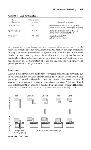
or with a socket. Some common lead types are shown in Fig. 10-4.
Pin Gull-wing J-bend Ball Land
Package leads
Package on board
Through hole
technology (THT) Surface mount technology (SMT)
Figure 10-4 Lead types.