
Page 392 - Microsensors, MEMS and Smart Devices - Gardner Varadhan and Awadelkarim
P. 392
372 IDT MICROSENSORS
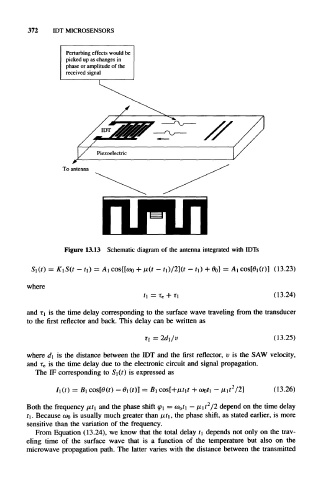
Perturbing effects would be
picked up as changes in
phase or amplitude of the
received signal
To antenna
Figure 13.13 Schematic diagram of the antenna integrated with IDTs
S,(0 = KiS(t - ti) = Ai cos{[a> + u(t - fi)/2](r - t 1,) + 0 0} = A, cos[6>i(r)] (13.23)
where
f i = T e + (13.24)
and TI is the time delay corresponding to the surface wave traveling from the transducer
to the first reflector and back. This delay can be written as
T }=2di/v (13.25)
where d\ is the distance between the IDT and the first reflector, i> is the SAW velocity,
and T e is the time delay due to the electronic circuit and signal propagation.
The IF corresponding to S 1 (t) is expressed as
(13.26)
2
Both the frequency t 1 and the phase shift 1 = a> 0t\ - n\t /2 depend on the time delay
ri. Because CDQ is usually much greater than , the phase shift, as stated earlier, is more
sensitive than the variation of the frequency.
From Equation (13.24), we know that the total delay t\ depends not only on the trav-
eling time of the surface wave that is a function of the temperature but also on the
microwave propagation path. The latter varies with the distance between the transmitted