
Page 391 - Microsensors, MEMS and Smart Devices - Gardner Varadhan and Awadelkarim
P. 391
APPLICATIONS 371
0.001
0.000
-0.001
-0.002
Ml ' M M M M
10 12 14 16 18 20
Time (s)
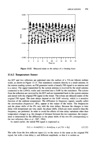
Figure 13.12 Measured strain on the surface of a vibrating beam
13.4.2 Temperature Sensor
An IDT and two reflectors are patterned onto the surface of a YZ-cut lithium niobate
wafer, as shown in Figure 13.13. This transducer connects directly to a small antenna. In
the remote reading system, an FM generator sends a linearly FM signal to an antenna and
to a mixer. The signal transmitted by the system antenna is received by the small antenna
connected to the LiNbOa wafer and converted into a SAW by the transducer. The echoes
from the reflectors are received by the IDT and are transmitted back to the system antenna
and mixed with the original FM signal in the mixer. The echoes are delayed copies of the
original FM signal. The time delays depend on the SAW velocity, which is a sensitive
function of the ambient temperature. The difference in frequency signals, usually called
the intermediate frequencies (IPs), appear at the output of the mixer. The frequencies
and the phase shifts of the IFs vary with the time delays. Because the changes in time
delay with temperature are very small, the phase shifts, which are more sensitive than the
frequency, are preferred. In order to avoid the effects of time delay variations other than
temperature changes (e.g. the changes of distance between the two antennae), the temper-
ature is determined by the difference in the phase shifts of the two IFs corresponding to
the two reflectors (Bao et al. 1987, 1994).
As stated earlier, the initial FM signal is expressed as
S(t) = A cos[0(f)] = A cos[(wo + 2)t + 0 0] (13.22)
The echo from the first reflector input (SO to the mixer is the same as the original FM
signal, but with a time delay t\ and different amplitude, so that it is written as