
Page 386 - Microsensors, MEMS and Smart Devices - Gardner Varadhan and Awadelkarim
P. 386
366 IDT MICROSENSORS
The echoes from the two reflectors are picked up by the antenna-IDT and sent back to
the system antenna. The echo signals are delayed copies of the transmitted FM signal. The
delay times mainly depend on the velocity of the SAW and the distance between the IDT
and the reflectors. A mixer, which takes the transmitted FM as a reference signal, outputs
the signals of frequency difference between the reflected and the transmitted signals.
Because the transmitted signal is linearly FM, the frequency difference is proportional to
the time delay. By using a spectrum analysis technique, such as a fast fourier transform
(FFT), the two echo signals can be separated in the frequency domain because the delay
times are different.
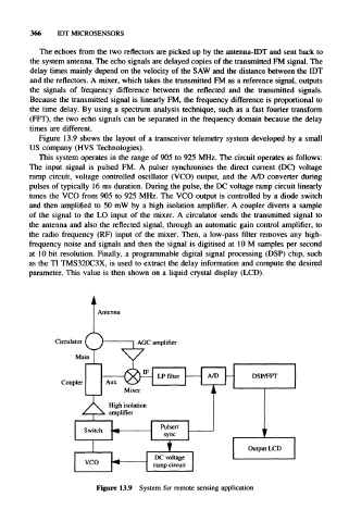
Figure 13.9 shows the layout of a transceiver telemetry system developed by a small
US company (HVS Technologies).
This system operates in the range of 905 to 925 MHz. The circuit operates as follows:
The input signal is pulsed FM. A pulser synchronises the direct current (DC) voltage
ramp circuit, voltage controlled oscillator (VCO) output, and the A/D converter during
pulses of typically 16 ms duration. During the pulse, the DC voltage ramp circuit linearly
tunes the VCO from 905 to 925 MHz. The VCO output is controlled by a diode switch
and then amplified to 50 mW by a high isolation amplifier. A coupler diverts a sample
of the signal to the LO input of the mixer. A circulator sends the transmitted signal to
the antenna and also the reflected signal, through an automatic gain control amplifier, to
the radio frequency (RF) input of the mixer. Then, a low-pass filter removes any high-
frequency noise and signals and then the signal is digitised at 10 M samples per second
at 10 bit resolution. Finally, a programmable digital signal processing (DSP) chip, such
as the TI TMS320C3X, is used to extract the delay information and compute the desired
parameter. This value is then shown on a liquid crystal display (LCD).
DSP/FFT
i
Output LCD
Figure 13.9 System for remote sensing application