
Page 381 - Microsensors, MEMS and Smart Devices - Gardner Varadhan and Awadelkarim
P. 381
SAW DEVICE MODELING VIA COUPLED-MODE THEORY 361
Figure 13.1 shows the actual device layout that has a metallic IDT, metallic reflector,
1
and spacing in between on top of a piezoelectric substrate . Thus, they can be represented,
as shown in Figure 13.2, with transfer matrices T, D, and G for each element of the SAW
device (the numbers 1, 2, and 3 are shown for bookkeeping purposes when dual devices
or even array devices are modeled).
The electrical signals passing in and out of the IDT are represented by the scalars a
and h. The SAWs coming in and out of each representative element are described by the
+
symbols W and ~W - one for each propagation direction. Thus, any (n — l)th SAW
amplitude coming in and out of the nth section (T, D, or G) has the following relation,
where the components of the transfer matrices are represented by italic typeface.
(13.2)
This matrix representation of a lumped system model of a SAW device allows other
SAW structures to be modeled as well. As long as the SAW device is a combination
of IDT, reflectors, and spacings, corresponding transfer matrices can be used in the
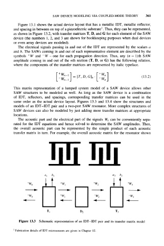
same order as the actual device layout. Figures 13.3 and 13.4 show the structures and
models of an IDT-IDT pair and a two-port SAW resonator. More complex structures of
SAW devices can also be modeled by just adding more transfer matrices at appropriate
locations.
The acoustic part and the electrical part of the signals W i can be conveniently sepa-
rated for the IDT equations and hence solved to determine the SAW amplitudes. Then,
the overall acoustic part can be represented by the simple product of each acoustic
transfer matrix in turn. For example, the overall acoustic matrix for the resonator shown
"3 U 3
it
W,
Figure 13.3 Schematic representation of an IDT-IDT pair and its transfer matrix model
1
Fabrication details of IDT microsensors are given in Chapter 12.