
Page 382 - Microsensors, MEMS and Smart Devices - Gardner Varadhan and Awadelkarim
P. 382
362 IDT MICROSENSORS
+
W
-
W
G D T D T D G
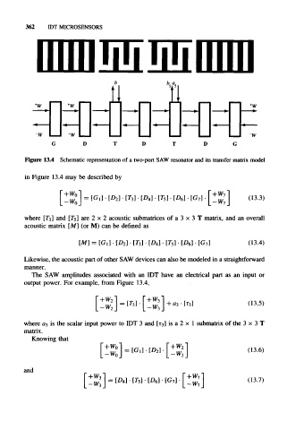
Figure 13.4 Schematic representation of a two-port SAW resonator and its transfer matrix model
in Figure 13.4 may be described by
= [G,]-[D 2 ] [D 4] • [T 5] • [D 6] • [G 7] (13.3)
where [T3] and [75] are 2 x 2 acoustic submatrices of a 3 x 3 T matrix, and an overall
acoustic matrix [M] (or M) can be defined as
[M] = [G 1] • [D 2] • [T 3] • [D 4] • T 5 • [D 6] • [G 7] (13.4)
Likewise, the acoustic part of other SAW devices can also be modeled in a straightforward
manner.
The SAW amplitudes associated with an IDT have an electrical part as an input or
output power. For example, from Figure 13.4,
(13.5)
where 03 is the scalar input power to IDT 3 and [t3] is a 2 x 1 submatrix of the 3 x 3 T
matrix.
Knowing that
r_LMA,i r.uu/^1
(13.6)
and
(13.7)