
Page 383 - Microsensors, MEMS and Smart Devices - Gardner Varadhan and Awadelkarim
P. 383
SAW DEVICE MODELING VIA COUPLED-MODE THEORY 363
substituting Equations (13.6) and (13.7) into Equation (13.5) gives an overall transfer
matrix of the SAW device in terms of W0'S and W7's for a given input #3, as shown in
the following equation:
[M] a 3 - [ G i ] - [ D 2 ] ' [ T 3 ] (13.8)
By applying the appropriate boundary conditions, Equation (13.8) becomes soluble with
two subequations and two unknown parameters. Usually, the boundary conditions are
W 0 = 0 and — W 7 = 0 because there are no external sources to SAWs, that is, from
outside the device. Any reflections of the SAWs from the substrate edges, or other struc-
tures outside the SAW device, are suppressed by using an acoustic absorber and/or serrated
(or slanted) edges.
The basic form of the transfer matrices remains the same for other devices, whereas
some of the parameters inside the transfer matrix are changed according to the choice of
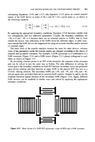
material and geometric constants. For example, a SAW gyroscope is a combination of a
SAW resonator (Figure 13.4) and a SAW sensor (Figure 13.1) placed orthogonal to each
other, as shown in Figure 13.5.
By providing a known power to an IDT of the resonator, the response of the resonator
part can be solved in just the same way as before. The only difference in solving the
sensor part is the boundary condition on each IDT because secondary waves are generated
upon device rotation and they become an input SAW to the passive IDT that acts as a
Coriolis sensing element. The secondary SAWs are +W 2 and —W 1 and +Wo and — W 3
and are again zero, provided there are no external SAW sources. Outputs b\ and b 3 are the
resultant electrical signals because of the secondary SAW (Figure 13.6). Again, different
SAW devices can be modeled in similar ways and solved by applying the appropriate
boundary conditions.
m
Figure 13.5 Basic layout of a SAW-IDT gyroscope: a pair of IDTs and a SAW resonator