
Page 380 - Microsensors, MEMS and Smart Devices - Gardner Varadhan and Awadelkarim
P. 380
360 IDT MICROSENSORS
Because the change in acoustic velocity of a SAW microsensor is a combination of these
different parameters, care must be taken in the choice of IDT design and signal processing
techniques so that only changes in the desired parameter, such as mass, are measured and
not the cross-interfering signals from, for example, mechanical strain or environmental
temperature. The coupled-mode theory of SAW devices helps us to understand the nature
of these types of microsensors.
13.2 SAW DEVICE MODELING VIA COUPLED-MODE
THEORY
The use of coupled-mode theory on SAW devices for different geometric designs and
choice of piezoelectric material is clearly described by Pierce (1954) and Campbell (1998).
The benefit of this approach is that a SAW device can be represented by a set of transfer
matrices corresponding to its basic elements.
There are generally three elements of a SAW device: IDT, spacing, and reflector. These
can be described by the transfer matrices of T, D, and G, respectively. T matrix is a 3 x 3
matrix, whereas D and G are 2 x 2 matrices. The T matrix describes the IDT input and
output of SAWs as well as the electromechanical conversion between the electrical signal
and the SAW. Thus, the T matrix has three ports of which two are acoustical ports and one
is an electrical port. The transfer matrix D describes a SAW propagation path between two
representative sections, while matrix G represents a reflector array. Detailed mathematical
forms of these transfer matrices are given in Appendix J.
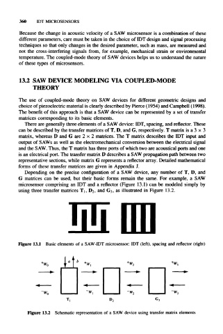
Depending on the precise configuration of a SAW device, any number of T, D, and
G matrices can be used, but their basic forms remain the same. For example, a SAW
microsensor comprising an IDT and a reflector (Figure 13.1) can be modeled simply by
using three transfer matrices TI, D2, and G 3, as illustrated in Figure 13.2.
Figure 13.1 Basic elements of a SAW-IDT microsensor: IDT (left), spacing and reflector (right)
Figure 13.2 Schematic representation of a SAW device using transfer matrix elements