
Page 385 - Microsensors, MEMS and Smart Devices - Gardner Varadhan and Awadelkarim
P. 385
WIRELESS SAW-BASED MICROSENSORS 365
Amplifier
Frequency
counter
IDT IDT
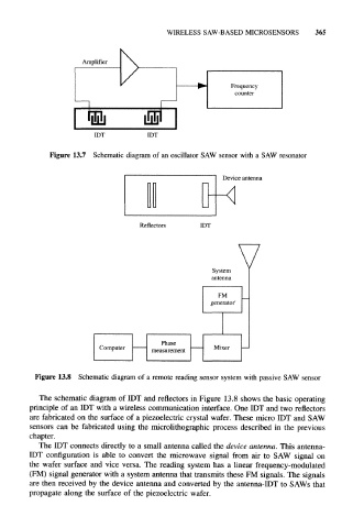
Figure 13.7 Schematic diagram of an oscillator SAW sensor with a SAW resonator
Device antenna
Reflectors IDT
Figure 13.8 Schematic diagram of a remote reading sensor system with passive SAW sensor
The schematic diagram of IDT and reflectors in Figure 13.8 shows the basic operating
principle of an IDT with a wireless communication interface. One IDT and two reflectors
are fabricated on the surface of a piezoelectric crystal wafer. These micro IDT and SAW
sensors can be fabricated using the microlithographic process described in the previous
chapter.
The IDT connects directly to a small antenna called the device antenna. This antenna-
IDT configuration is able to convert the microwave signal from air to SAW signal on
the wafer surface and vice versa. The reading system has a linear frequency-modulated
(FM) signal generator with a system antenna that transmits these FM signals. The signals
are then received by the device antenna and converted by the antenna-IDT to SAWs that
propagate along the surface of the piezoelectric wafer.