
Page 269 - Modern Control Systems
P. 269
Section 4.4 Disturbance Signals in a Feedback Control System 243
radar antennas are subjected to wind gusts; and many systems generate unwanted
distortion signals due to nonlinear elements. The benefit of feedback systems is that
the effect of distortion, noise, and unwanted disturbances can be effectively reduced.
Disturbance Rejection
When R(s) = N(s) = 0, it follows from Equation (4.4) that
G(s)
E(s) = S(s)G(s)T d(s) Us)-
1 + L(s)
For a fixed G(s) and a given 7^(^), as the loop gain L(s) increases, the effect of T d(s)
on the tracking error decreases. In other words, the sensitivity function S(s) is small
when the loop gain is large. We say that large loop gain leads to good disturbance re-
jection. More precisely, for good disturbance rejection, we require a large loop gain
over the frequencies of interest associated with the expected disturbance signals.
In practice, the disturbance signals are often low frequency. When that is the
case, we say that we want the loop gain to be large at low frequencies. This is equiv-
alent to stating that we want to design the controller G c(s) so that the sensitivity
function S(s) is small at low frequencies.
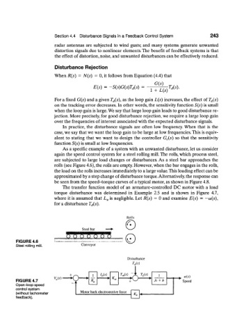
As a specific example of a system with an unwanted disturbance, let us consider
again the speed control system for a steel rolling mill. The rolls, which process steel,
are subjected to large load changes or disturbances. As a steel bar approaches the
rolls (see Figure 4.6), the rolls are empty. However, when the bar engages in the rolls,
the load on the rolls increases immediately to a large value. This loading effect can be
approximated by a step change of disturbance torque. Alternatively, the response can
be seen from the speed-torque curves of a typical motor, as shown in Figure 4.8.
The transfer function model of an armature-controlled DC motor with a load
torque disturbance was determined in Example 2.5 and is shown in Figure 4.7,
where it is assumed that L a is negligible. Let R(s) = 0 and examine E(s) = — a)(s),
for a disturbance T (!(s).
Rolls
0
Steel bar
AAftM^
FIGURE 4.6 ©
Conveyor
Steel rolling mill.
Disturbance
1 W r„,(.*) t T L(S)
W t » <o(s)
FIGURE 4.7 Js + b Speed
Open-loop speed
control system
(without tachometer Motor back electromotive force
feedback).