Page 271 - Modern Control Systems
P. 271

Section 4.4  Disturbance Signals in a Feedback  Control System       245
                            T,,{s)
                                                                         Tj{s)


                                                                                          *•  a)(s)

                            •H(s)

                        (a)                                           (b)

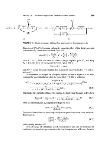
                        FIGURE 4.10  Closed-loop system, (a) Signal-flow graph model, (b) Block diagram model.

                        Therefore,  if  G x(s)H(s)  is made  sufficiently  large, the  effect  of the  disturbance  can
                        be decreased  by closed-loop feedback. Note  that

                                                     KgK m       Kb
                                         G^His)
                                                      R„
                        since  K a  ^>  K b.  Thus,  we  strive  to  obtain  a  large  amplifier  gain,  K a,  and  keep
                           <  2 CI. The error  for  the system shown in Figure 4.10 is
                        R a
                                                   E(s)  =  R(s)  -  (o(s),

                        and  R(s)  =  (o^s),  the  desired  speed. For  calculation  ease, we let  R(s)  =  0 and  ex-
                        amine  a>(s).
                            To  determine  the  output  for  the  speed  control  system  of  Figure  4.9, we  must
                        consider  the load  disturbance when the input  R(s)  =  0. This is written  as
                                                     -1/(/5  +  b)
                           (o(s)  =                                                 Us)
                                  1  +  (K tK aK m/R a)[\/(Js  +  b)]  +  (K mK h/R a)[\/{Js  + b)]
                                              - 1
                                                             •Us)-                         (4.30)
                                  Js  +  b  +  (KJR (l)(K tK a  +  K b)
                        The steady-state output is obtained  by utilizing the final-value  theorem, and  we have
                                                                     - 1
                                     limco(/)  =  limfaufc))  = ,  .„  ._  W r ,  .,  D\   (431)
                                    ^oo       s ^     })  b  +  (KjR a)(K tK a  +  K h)

                        when the  amplifier  gain K a  is sufficiently  high, we have
                                               w(co)       ^-D   =  o, c(oo).              (4.32)
                                                         -R n
                                                       K aK niK t
                        The ratio of closed-loop to open-loop steady-state speed output due to an undesired
                                                       p steady-
                        disturbance  is
                                                  w c(oo)  RJb  +  K mK b
                                                                                           (4.33)
                                                  w 0(oo)    KaK mK,
                        and  is usually less than  0.02.
                            This  advantage  of  a  feedback  speed  control  system  can  also  be  illustrated  by
                        considering the speed-torque  curves for the closed-loop system, which are shown  in
   266   267   268   269   270   271   272   273   274   275   276