
Page 275 - Modern Control Systems
P. 275
Section 4.5 Control of the Transient Response 249
Amplifier KM) Motor Speed
= M ^ Q »
• ^
R{s) J * G(s)
V t(s) Tachometer
*/
(a)
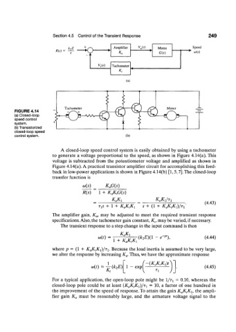
FIGURE 4.14
(a) Closed-loop
speed control
system.
(b) Transistorized
closed-loop speed
control system. (b)
A closed-loop speed control system is easily obtained by using a tachometer
to generate a voltage proportional to the speed, as shown in Figure 4.14(a). This
voltage is subtracted from the potentiometer voltage and amplified as shown in
Figure 4.14(a). A practical transistor amplifier circuit for accomplishing this feed-
back in low-power applications is shown in Figure 4.14(b) [1,5,7]. The closed-loop
transfer function is
K aG(s)
R(s) 1 + K aK tG{s)
K aKi * « * I / T I
(4.43)
T XS + 1 + KaKfo s + (l + KJCtKJ/Ti
The amplifier gain, K a, may be adjusted to meet the required transient response
specifications. Also, the tachometer gain constant, K t, may be varied, if necessary.
The transient response to a step change in the input command is then
K aKi
a(t) = (k 2E)(\ - *-"), (4.44)
1 + K aK tK x
where p = (1 + K aK tK {)/Ti. Because the load inertia is assumed to be very large,
we alter the response by increasing K a. Thus, we have the approximate response
J_ (KaKKJt
io{t) (k 2E) 1 — exp (4.45)
K t
For a typical application, the open-loop pole might be 1/TT = 0.10, whereas the
closed-loop pole could be at least (K aK tKi)/T] = 10, a factor of one hundred in
the improvement of the speed of response. To attain the gain K aK tK h the ampli-
fier gain K a must be reasonably large, and the armature voltage signal to the