
Page 280 - Modern Control Systems
P. 280
Chapter 4 Feedback Control System Characteristics
G{s) equal to 1, we imply that the output is directly connected to the input. We must
recall that a specific output (such as temperature, shaft rotation, or engine speed), is
desired, whereas the input can be a potentiometer setting or a voltage. The process
G(s) is necessary to provide the physical process between R(s) and Y(s). Therefore,
a transfer function G(s) = 1 is unrealizable, and we must settle for a practical trans-
fer function.
4.8 DESIGN EXAMPLES
In this section we present three illustrative examples: the English Channel boring
machine, the Mars rover, and a blood pressure control problem during anesthesia.
The English Channel boring machine example focuses on the closed-loop system
response to disturbances. The Mars rover example highlights the advantages of
closed-loop feedback control in decreasing system sensitivity to plant changes. The
final example on blood pressure control is a more in-depth look at the control
design problem. Since patient models in the form of transfer functions are diffi-
cult to obtain from basic biological and physical principles, a different approach
using measured data is discussed. The positive impact of closed-loop feedback control
is illustrated in the context of design.
EXAMPLE 4.2 English Channel boring machines
The construction of the tunnel under the English Channel from France to Great
Britain began in December 1987. The first connection of the boring tunnels from
each country was achieved in November 1990. The tunnel is 23.5 miles long and is
bored 200 feet below sea level. The tunnel, completed in 1992 at a total cost of $14
billion, accommodates 50 train trips daily. This construction is a critical link between
Europe and Great Britain, making it possible for a train to travel from London to
Paris in three hours.
The machines, operating from both ends of the channel, bored toward the mid-
dle. To link up accurately in the middle of the channel, a laser guidance system kept
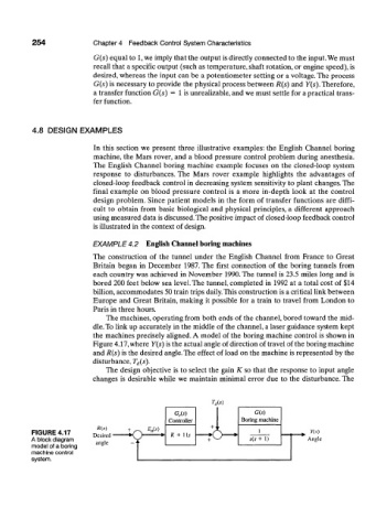
the machines precisely aligned. A model of the boring machine control is shown in
Figure 4.17, where Y(s) is the actual angle of direction of travel of the boring machine
and R(s) is the desired angle. The effect of load on the machine is represented by the
disturbance, T d(s).
The design objective is to select the gain K so that the response to input angle
changes is desirable while we maintain minimal error due to the disturbance. The
W
G c(s) G(s)
Controller Boring machine
R{s) E ais) +J r
FIGURE 4.17 Desired K + Ms 1 Y(s)
A block diagram angle + ^-^ s(s + 1) Angle
model of a boring
machine control