
Page 282 - Modern Control Systems
P. 282
256 Chapter 4 Feedback Control System Characteristics
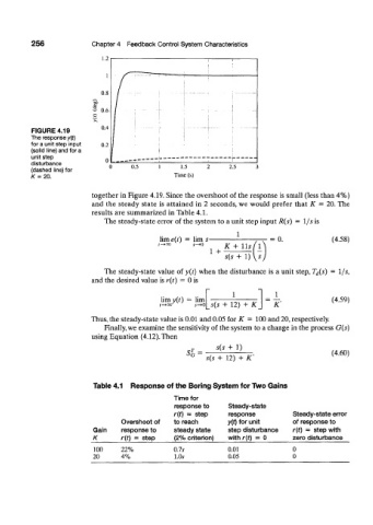
FIGURE 4.19
The response y{t)
for a unit step input
(solid line) and for a
unit step
disturbance
(dashed line) for
K=20.
together in Figure 4.19. Since the overshoot of the response is small (less than 4%)
and the steady state is attained in 2 seconds, we would prefer that K = 20. The
results are summarized in Table 4.1.
The steady-state error of the system to a unit step input R(s) = \fs is
lim e(t) = lim s- = 0. (4.58)
K + llsfl
1 +
\
s(s + 1) s
The steady-state value of y(t) when the disturbance is a unit step, T d(s) = 1/s,
and the desired value is r(t) = 0 is
1_
limy(r) = lim (4.59)
s(s + 12) + K K'
Thus, the steady-state value is 0.01 and 0.05 for K = 100 and 20, respectively.
Finally, we examine the sensitivity of the system to a change in the process G(s)
using Equation (4.12). Then
s(s + 1)
SL = (4.60)
s(s + 12) + K'
Table 4.1 Response of the Boring System for Two Gains
Time for
response to Steady-state
r(f) = step response Steady-state error
Overshoot of to reach y(t) for unit of response to
Gain response to steady state step disturbance r{t) = step with
K r(t) - step (2% criterion) with r(t) = 0 zero disturbance
100 22% 0.7s 0.01 0
20 4% 1.0A- 0.05 0