
Page 104 - Modern Control of DC-Based Power Systems
P. 104
68 Modern Control of DC-Based Power Systems
conversion function. In fact, it is possible to integrate these digital net-
work analyzer techniques [48] into the converter controllers allowing
them to be used as online monitors without any extra power hardware.
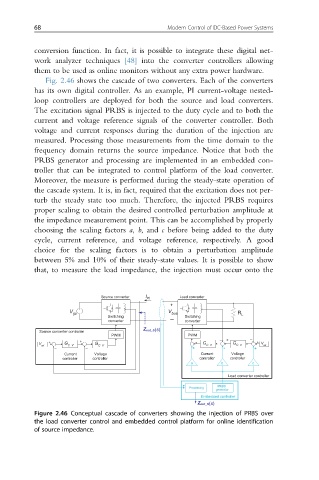
Fig. 2.46 shows the cascade of two converters. Each of the converters
has its own digital controller. As an example, PI current-voltage nested-
loop controllers are deployed for both the source and load converters.
The excitation signal PRBS is injected to the duty cycle and to both the
current and voltage reference signals of the converter controller. Both
voltage and current responses during the duration of the injection are
measured. Processing those measurements from the time domain to the
frequency domain returns the source impedance. Notice that both the
PRBS generator and processing are implemented in an embedded con-
troller that can be integrated to control platform of the load converter.
Moreover, the measure is performed during the steady-state operation of
the cascade system. It is, in fact, required that the excitation does not per-
turb the steady state too much. Therefore, the injected PRBS requires
proper scaling to obtain the desired controlled perturbation amplitude at
the impedance measurement point. This can be accomplished by properly
choosing the scaling factors a, b, and c before being added to the duty
cycle, current reference, and voltage reference, respectively. A good
choice for the scaling factors is to obtain a perturbation amplitude
between 5% and 10% of their steady-state values. It is possible to show
that, to measure the load impedance, the injection must occur onto the
Source converter I inj Load converter
+
V gs V bus R
Switching Switching L
converter – converter
Z out_S(s)
Source converter controller
PWM PWM
– + –
+
V + G G + G G + V
ref C_V C_V C_V C_V ref
– – + + +
Current Voltage Current Voltage
controller controller controller controller
a b c
Load converter controller
PRBS
Processing
generator
Embedded controller
Z out_S(s)
Figure 2.46 Conceptual cascade of converters showing the injection of PRBS over
the load converter control and embedded control platform for online identification
of source impedance.