
Page 106 - Modern Control of DC-Based Power Systems
P. 106
70 Modern Control of DC-Based Power Systems
• If PRBS 2 (or PRBS 3 ) is applied, v has the same amplitude of the
injected disturbance within the frequency range where T I (or T V )is
very large, i.e., within the control bandwidth, while is reduced in
amplitude at larger frequencies.
In other words, if PRBS is injected to the duty cycle only, PRBS,
seen as a disturbance, is rejected within the bandwidth of the selected
control loop (either current or voltage), while it is not rejected beyond
the bandwidth of the selected control loop. On the other hand, if PRBS
is injected to the current or voltage reference signals, it is not rejected
within the bandwidth of the selected current or voltage control loop,
respectively. Therefore, injecting PRBS to the duty cycle and to either
the current or the voltage reference signals ensures that PRBS is not
rejected by the selected control action over a wide frequency range.
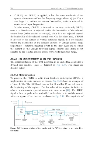
2.6.2.1 The Implementation of the WSI Technique
The implementation of the WSI algorithm in an embedded controller is
divided into multiple stages as depicted in Fig. 2.47. The stages are
detailed below.
2.6.2.1.1 PRBS Generation
To generate the PRBS, a x-bit linear feedback shift-register (LFSR) is
implemented at a rate that can be chosen. Fig. 2.48 shows an example of
a 15-bit LFSR. The XOR-ed value of bit 14 and bit 15 are fed back to
the beginning of the register. The last value of the register is shifted to
achieve a white-noise approximation with zero mean [47]. The PRBS
signal is then properly scaled and added to the duty cycles and the control
reference signals of the inverter, as shown in Fig. 2.46. The amplitude of
V, I
Calculation
Figure 2.47 Implementation of the routines of the WSI technique in an embedded
controller.