
Page 105 - Modern Control of DC-Based Power Systems
P. 105
Small-Signal Analysis of Cascaded Systems 69
source converter control. The reader can easily draw the schematic to
measure the load impedance and this is left as an exercise.
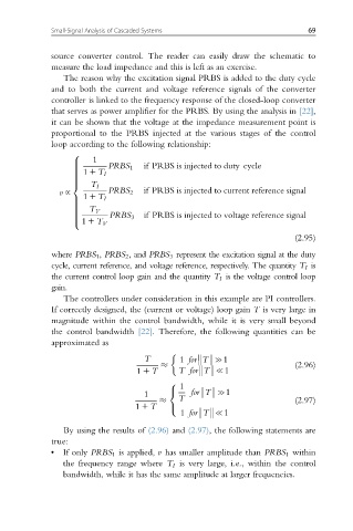
The reason why the excitation signal PRBS is added to the duty cycle
and to both the current and voltage reference signals of the converter
controller is linked to the frequency response of the closed-loop converter
that serves as power amplifier for the PRBS. By using the analysis in [22],
it can be shown that the voltage at the impedance measurement point is
proportional to the PRBS injected at the various stages of the control
loop according to the following relationship:
8
1
> if PRBS is injected to duty cycle
> PRBS 1
>
1 1 T I
>
>
>
>
>
T I
<
v ~ PRBS 2 if PRBS is injected to current reference signal
1 1 T I
>
>
>
T V
>
>
> if PRBS is injected to voltage reference signal
PRBS 3
>
>
1 1 T V
:
(2.95)
where PRBS 1 , PRBS 2 ,and PRBS 3 represent the excitation signal at the duty
cycle, current reference, and voltage reference, respectively. The quantity T I is
the current control loop gain and the quantity T I is the voltage control loop
gain.
The controllers under consideration in this example are PI controllers.
If correctly designed, the (current or voltage) loop gain T is very large in
magnitude within the control bandwidth, while it is very small beyond
the control bandwidth [22]. Therefore, the following quantities can be
approximated as
T 1 for:T:c1
(2.96)
1 1 T T for:T:{1
1
8
1 < for:T:c1
T (2.97)
1 1 T :
1 for:T:{1
By using the results of (2.96) and (2.97), the following statements are
true:
• If only PRBS 1 is applied, v has smaller amplitude than PRBS 1 within
the frequency range where T I is very large, i.e., within the control
bandwidth, while it has the same amplitude at larger frequencies.