
Page 107 - Modern Control of DC-Based Power Systems
P. 107
Small-Signal Analysis of Cascaded Systems 71
a
1 t
–a
t
a
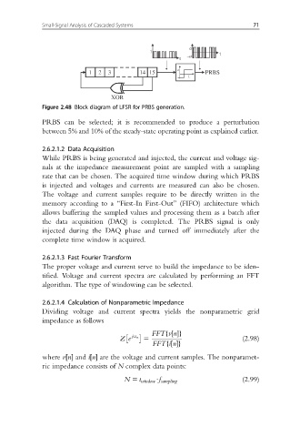
1 2 3 14 15 PRBS
1
XOR
Figure 2.48 Block diagram of LFSR for PRBS generation.
PRBS can be selected; it is recommended to produce a perturbation
between 5% and 10% of the steady-state operating point as explained earlier.
2.6.2.1.2 Data Acquisition
While PRBS is being generated and injected, the current and voltage sig-
nals at the impedance measurement point are sampled with a sampling
rate that can be chosen. The acquired time window during which PRBS
is injected and voltages and currents are measured can also be chosen.
The voltage and current samples require to be directly written in the
memory according to a “First-In First-Out” (FIFO) architecture which
allows buffering the sampled values and processing them as a batch after
the data acquisition (DAQ) is completed. The PRBS signal is only
injected during the DAQ phase and turned off immediately after the
complete time window is acquired.
2.6.2.1.3 Fast Fourier Transform
The proper voltage and current serve to build the impedance to be iden-
tified. Voltage and current spectra are calculated by performing an FFT
algorithm. The type of windowing can be selected.
2.6.2.1.4 Calculation of Nonparametric Impedance
Dividing voltage and current spectra yields the nonparametric grid
impedance as follows
FFTfvn ½g
Ze jω n 5 (2.98)
FFTfin ½g
where v½n and i½n are the voltage and current samples. The nonparamet-
ric impedance consists of N complex data points:
N 5 t window Uf sampling (2.99)