
Page 174 - Modern Control of DC-Based Power Systems
P. 174
138 Modern Control of DC-Based Power Systems
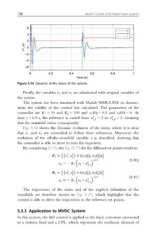
Figure 5.14 Dynamic of the states of the system.
Finally, the variables v 1 and v 2 are substituted with original variables of
the system.
The system has been simulated with Matlab/SIMULINK to demon-
strate the validity of the control law calculated. The parameters of the
controller are K 1 5 10 and K 2 5 100 and x 1 0ðÞ 5 0:5 and x 2 0ðÞ 5 0. At
time t 5 0.5 s, the reference is varied from x 5 2to x 5 3, meaning
1;1 1;2
that the manifold varies consequently.
Fig. 5.14 shows the dynamic evolution of the states, where it is clear
that x 1 and x 2 are controlled to follow their references. Moreover, the
evolution of the off-the-manifold variable z is described, showing that
the controller is able to drive to zero the trajectory.
By considering (5.71),the Eq. (5.77) for the different set-points results in:
1
Φ 1 5 v ; v 2 1 5 π 1 ξðÞ; π 2 ξðÞð Þ
1
2=3
(5.80)
x 2 52 K 1 x 1 2x
1;1
2
Φ 2 5 v ; v 2
1 2 5 π 1 ξðÞ; π 2 ξðÞð Þ
2=3
(5.81)
x 2 52 K 1 x 1 2x
1;2
The trajectories of the states and of the implicit definition of the
manifolds are therefore shown in Fig. 5.15, which highlights that the
control is able to drive the trajectories to the reference set-points.
5.3.3 Application to MVDC System
In this section, the I&I control is applied to the buck converter connected
to a resistive load and a CPL, which represents the nonlinear element of