
Page 177 - Modern Control of DC-Based Power Systems
P. 177
Control Approaches for Parallel Source Converter Systems 141
I
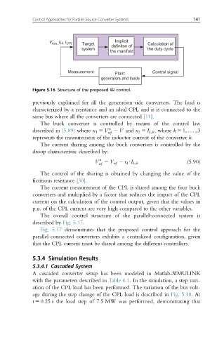
V bus, Lk, I CPL Target Implicit Calculation of
definiton of
system the duty cycle
the manifold
Measurement Plant: Control signal
generators and loads
Figure 5.16 Structure of the proposed I&I control.
previously explained for all the generation-side converters. The load is
characterized by a resistance and an ideal CPL and it is connected to the
same bus where all the converters are connected [11].
The buck converter is controlled by means of the control law
described in (5.89) where x 1 5 V 2 V and x 2 5 I L;k , where k 5 1; .. . ; 3
ref
represents the measurement of the inductor current of the converter k.
The current sharing among the buck converters is controlled by the
droop characteristic described by:
(5.90)
V 5 V ref 2 r d UI L;k
ref
The control of the sharing is obtained by changing the value of the
fictitious resistance [30].
The current measurement of the CPL is shared among the four buck
converters and multiplied by a factor that reduces the impact of the CPL
current on the calculation of the control output, given that the values in
p.u. of the CPL current are very high compared to the other variables.
The overall control structure of the parallel-connected system is
described by Fig. 5.17.
Fig. 5.17 demonstrates that the proposed control approach for the
parallel-connected converters exhibits a centralized configuration, given
that the CPL current must be shared among the different controllers.
5.3.4 Simulation Results
5.3.4.1 Cascaded System
A cascaded converter setup has been modeled in Matlab-SIMULINK
with the parameters described in Table 6.1. In the simulation, a step vari-
ation of the CPL load has been performed. The variation of the bus volt-
age during the step change of the CPL load is described in Fig. 5.18.At
t 5 0.25 s the load step of 7.5 MW was performed, demonstrating that