
Page 240 - Modern Control of DC-Based Power Systems
P. 240
204 Modern Control of DC-Based Power Systems
L I L I R
I C
V in V C V bus
C R L
x 2 –1/C measurement
Current
Controller V ref
x 1
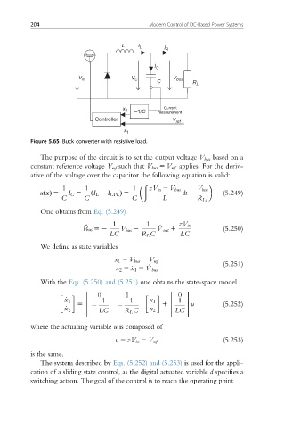
Figure 5.65 Buck converter with resistive load.
The purpose of the circuit is to set the output voltage V bus based on a
constant reference voltage V ref such that V bus 5 V ref applies. For the deriv-
ative of the voltage over the capacitor the following equation is valid:
ð
1 1 1 zV in 2 V bus V bus
u xðÞ 5 I C 5 ð I L 2 I CPL Þ 5 dt 2 (5.249)
C C C L R Ld
One obtains from Eq. (5.249)
€
V bus 52 1 V bus 2 1 _ V out 1 zV in (5.250)
LC R L C LC
We define as state variables
x 1 5 V bus 2 V ref
(5.251)
x 2 5 _x 1 5 _ V bus
With the Eqs. (5.250) and (5.251) one obtains the state-space model
2 3 2 3
0 1 0
_ x 1 1 1 x 1 1
5 4 2 2 5 1 4 5 u (5.252)
_ x 2 LC R L C x 2 LC
where the actuating variable u is composed of
u 5 zV in 2 V ref (5.253)
is the same.
The system described by Eqs. (5.252) and (5.253) is used for the appli-
cation of a sliding state control, as the digital actuated variable d specifies a
switching action. The goal of the control is to reach the operating point