
Page 245 - Modern Control of DC-Based Power Systems
P. 245
Control Approaches for Parallel Source Converter Systems 209
Current (p.u)
s(x)+β
s(x)-β
Voltage (p.u.)
Figure 5.69 Phase plot virtual distribution sliding mode cascaded Ideal CPL
Step 10.3 - 17.8 MW.
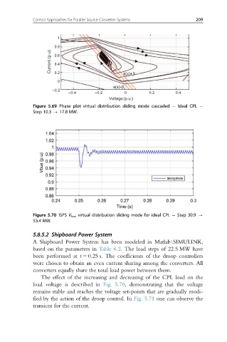
Figure 5.70 ISPS V bus virtual distribution sliding mode for ideal CPL Step 30.9 -
53.4 MW.
5.8.5.2 Shipboard Power System
A Shipboard Power System has been modeled in Matlab\SIMULINK,
based on the parameters in Table 6.2. The load steps of 22.5 MW have
been performed at t 5 0.25 s. The coefficients of the droop controllers
were chosen to obtain an even current sharing among the converters. All
converters equally share the total load power between them.
The effect of the increasing and decreasing of the CPL load on the
load voltage is described in Fig. 5.70, demonstrating that the voltage
remains stable and reaches the voltage set-points that are gradually modi-
fied by the action of the droop control. In Fig. 5.71 one can observe the
transient for the current.