
Page 257 - Modern Control of DC-Based Power Systems
P. 257
Simulation 221
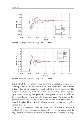
Figure 6.1 Voltage—ideal CPL—Step 10.3 - 17.8 MW.
Figure 6.2 Current—ideal CPL—Step 10.3 - 17.8 MW.
fastest of all the controllers while achieving a negligible overshoot of
0.0025 p.u. that is one decade better than the second best. The rise time
is faster than all the controllers which exhibit a bigger overshoot. The
Adaptive Backstepping controller features the lowest rise time, explained
by its error rate having an exponential convergence rate which is reflected
by no overshoot, but at a cost of a longer rise time. The perceived low
performance of the LSF lies solely on the chosen poles which link to a
desired damping. Hence, a trade-off between rise time and over-/under-
shoot is feasible.
A special attention should be also given to the estimates of the control
methods which use estimation techniques. In Fig. 6.3 the estimates of the
LQG virtual disturbance controller are depicted. In incidence of average