
Page 260 - Modern Control of DC-Based Power Systems
P. 260
224 Modern Control of DC-Based Power Systems
influence on the control loop of the LRC as explained in Chapter 2,
Small-Signal Analysis of Cascaded Systems. There is an interaction in
bandwidths of the two control systems. The virtual disturbance-based
controllers exhibit over-/undershoots similar in magnitude to in the ideal
CPL case although the transient time is slightly longer. An interesting
observation is that due to the PI control, the estimation error now con-
verges with fewer oscillations to its true value as presented in Fig. 6.6,
where the current exhibits for both virtual disturbance controllers, after
t 5 0.26, fewer oscillations until the final value is reached.
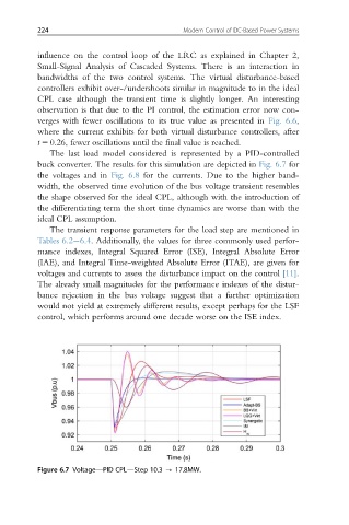
The last load model considered is represented by a PID-controlled
buck converter. The results for this simulation are depicted in Fig. 6.7 for
the voltages and in Fig. 6.8 for the currents. Due to the higher band-
width, the observed time evolution of the bus voltage transient resembles
the shape observed for the ideal CPL, although with the introduction of
the differentiating term the short time dynamics are worse than with the
ideal CPL assumption.
The transient response parameters for the load step are mentioned in
Tables 6.2 6.4. Additionally, the values for three commonly used perfor-
mance indexes, Integral Squared Error (ISE), Integral Absolute Error
(IAE), and Integral Time-weighted Absolute Error (ITAE), are given for
voltages and currents to assess the disturbance impact on the control [11].
The already small magnitudes for the performance indexes of the distur-
bance rejection in the bus voltage suggest that a further optimization
would not yield at extremely different results, except perhaps for the LSF
control, which performs around one decade worse on the ISE index.
Figure 6.7 Voltage—PID CPL—Step 10.3 - 17.8MW.