
Page 51 - Modern Control of DC-Based Power Systems
P. 51
16 Modern Control of DC-Based Power Systems
Switching converter
Power Load
input
V
V g R
Feedback
Transistor Compensator connection
gate driver
V
Pulse-width V c
δ(t) G c (s) -
modulator +
δ(t) V c Voltage
V ref
reference
dT T s t t
s
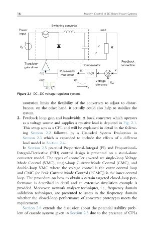
Figure 2.1 DC DC voltage regulator system.
saturation limits the flexibility of the converters to adjust to distur-
bances; on the other hand, it actually could also help to stabilize the
system.
2. Feedback loop gain and bandwidth: A buck converter which operates
as a voltage source and supplies a resistive load is depicted in Fig. 2.1.
This setup acts as a CPL and will be explained in detail in the follow-
ing Section 2.2 followed by a Cascaded System Evaluation in
Section 2.3 which is expanded to include the effects of a different
load model in Section 2.4.
In Section 2.5 practical Proportional-Integral (PI) and Proportional-
Integral-Derivative (PID) control design is presented on a stand-alone
converter model. The types of controller covered are single-loop Voltage
Mode Control (VMC), single-loop Current Mode Control (CMC), and
double-loop VMC where the voltage control is the outer control loop
and CMC (or Peak Current Mode Control (PCMC)) is the inner control
loop. The procedure on how to obtain a certain targeted closed-loop per-
formance is described in detail and an extensive simulation example is
provided. Moreover, network analyzer techniques, i.e., frequency domain
validation techniques, are presented to assess in the frequency domain
whether the closed-loop performance of converter prototypes meets the
requirements.
Section 2.6 extends the discussion about the potential stability prob-
lem of cascade systems given in Section 2.3 due to the presence of CPLs