
Page 56 - Modern Control of DC-Based Power Systems
P. 56
Small-Signal Analysis of Cascaded Systems 21
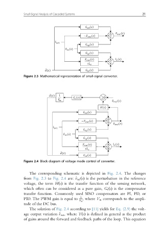
Figure 2.3 Mathematical representation of small-signal converter.
Figure 2.4 Block diagram of voltage mode control of converter.
The corresponding schematic is depicted in Fig. 2.4. The changes
from Fig. 2.3 to Fig. 2.4 are: ^v ref ðsÞ is the perturbation in the reference
voltage, the term HsðÞ is the transfer function of the sensing network,
which often can be considered as a pure gain, G c sðÞ is the compensator
transfer function. Commonly used SISO compensators are PI, PD, or
PID. The PWM gain is equal to 1 , where V m corresponds to the ampli-
V m
tude of the DC bus.
The solution of Fig. 2.4 according to [11] yields for Eq. (2.9) the volt-
age output variation ^ out , where TðsÞ is defined in general as the product
v
of gains around the forward and feedback paths of the loop. This equation